Design of Steel Reinforcement of Concrete Beams by WSD Method

Steps is for finding the required steel reinforcements of beam with known Mmax and other beam properties using Working Stress Design method.

Given the following, direct or indirect:

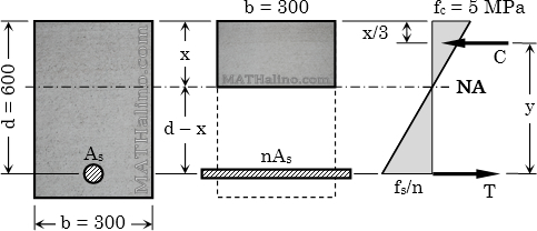
Width or breadth = b
Effective depth = d
Allowable stress for concrete = fc
Allowable stress for steel = fs
Modular ratio = n
Maximum moment carried by the beam = Mmax


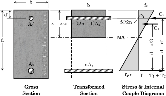
wsd-doubly-reinforced-beam.jpg

Working Stress Analysis for Concrete Beams

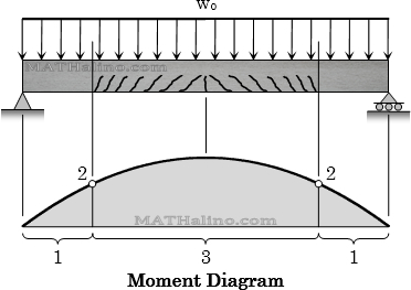
Consider a relatively long simply supported beam shown below. Assume the load wo to be increasing progressively until the beam fails. The beam will go into the following three stages:

  1. Uncrack Concrete Stage – at this stage, the gross section of the concrete will resist the bending which means that the beam will behave like a solid beam made entirely of concrete.
  2. Crack Concrete Stage – Elastic Stress range
  3. Ultimate Stress Stage – Beam Failure
wsd-beam-analysis-crack-uncrack.jpg


Consistency of Soil (Atterberg Limits)

Consistency is the term used to describe the ability of the soil to resist rupture and deformation. It is commonly describe as soft, stiff or firm, and hard.
 

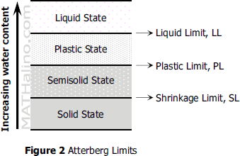
Water content greatly affects the engineering behavior of fine-grained soils. In the order of increasing moisture content (see Figure 2 below), a dry soil will exist into four distinct states: from solid state, to semisolid state, to plastic state, and to liquid state. The water contents at the boundary of these states are known as Atterberg limits. Between the solid and semisolid states is shrinkage limit, between semisolid and plastic states is plastic limit, and between plastic and liquid states is liquid limit.
 

002-atterberg-limits.gif


Atterberg limits, then, are water contents at critical stages of soil behavior. They, together with natural water content, are essential descriptions of fine-grained soils.
 

Physical Properties of Soil

Phase Diagram of Soil
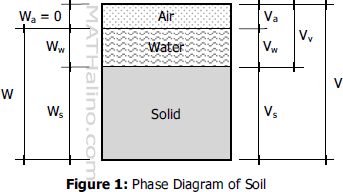
Soil is composed of solids, liquids, and gases. Liquids and gases are mostly water and air, respectively. These two (water and air) are called voids which occupy between soil particles. The figure shown below is an idealized soil drawn into phases of solids, water, and air.
 

001-phase-diagram-of-soil.gif


Weight-Volume Relationship from the Phase Diagram of Soil
total volume = volume of soilds + volume of voids
$V = V_s + V_v$

volume of voids = volume of water + volume of air
$V_v = V_w + V_a$

total weight = weight of solids + weight of water
$W = W_s + W_w$
 

Three Reservoirs Connected by Pipes at a Common Junction

Situation
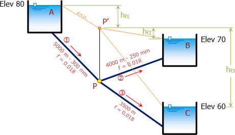
Three reservoirs A, B, and C are connected respectively with pipes 1, 2, and 3 joining at a common junction P. Reservoir A is at elevation 80 m, reservoir B at elevation 70 m and reservoir C is at elevation 60 m. The properties of each pipe are as follows:

Pipe 1:   L = 5000 m, D = 300 mm
Pipe 2:   L = 4000 m, D = 250 mm
Pipe 3:   L = 3500 m

The flow from reservoir A to junction P is 0.045 m3/s and f for all pipes is 0.018.
 

011-three-reservoir-problems.jpg


  1. Find the elevation of the energy grade line at P in m.
    A.   75.512
    B.   73.805
    C.   72.021
    D.   74.173
  2. Determine the flow on pipe 2 in m3/s.
    A.   0.025
    B.   0.031
    C.   0.029
    D.   0.036
  3. Compute the diameter appropriate for pipe 3 in mm.
    A.   175
    B.   170
    C.   178
    D.   172

Problem 20 - Bernoulli's Energy Theorem

Problem 20
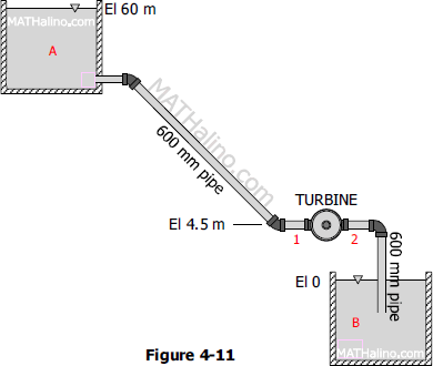
The 600-mm pipe shown in Figure 4-11 conducts water from reservoir A to a pressure turbine, which discharges through another 600-mm pipe into tailrace B. The loss of head from A to 1 is 5 times the velocity head in the pipe and the loss of head from 2 to B is 0.2 times the velocity head in the pipe. If the discharge is 700 L/s, what power is being given up by the water to the turbine and what are the pressure heads at 1 and 2?
 

04-014-flow-with-turbine.gif


Problem 19 - Bernoulli's Energy Theorem

Problem 19
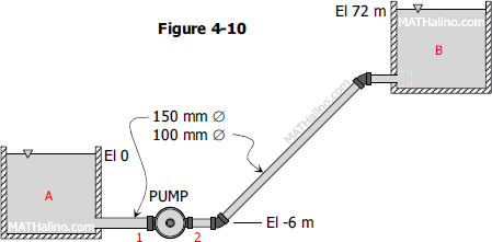
A pump draws water from reservoir A and lifts it to reservoir B as shown in Figure 4-10. The loss of head from A to 1 is 3 times the velocity head in the 150-mm pipe and the loss of head from 2 to B is 20 times the velocity head in the 100-mm pipe. Compute the horsepower output of the pump and the pressure heads at 1 and 2 when the discharge is: (a) 12 L/s; (b) 36 L/s.
 

04-013-flow-with-pump.gif


Problem 17 - Bernoulli's Energy Theorem

Problem 17
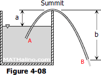
In Figure 4-08 is shown a siphon discharging water from reservoir A into the air at B. Distance 'a' is 1.8 m, 'b' is 6 m, and the diameter is 150 mm throughout. If there is a frictional loss of 1.5 m between A and the summit, and 1.5 m between the summit and B, what is the absolute pressure at the summit in kiloPascal? Also determine the rate of discharge in cubic meter per second and in gallons per minute.
 

04-011-siphon.gif


Problem 16 - Bernoulli's Energy Theorem

Problem 16
A pump (Figure 4-07) takes water from a 200-mm suction pipe and delivers it to a 150-mm discharge pipe in which the velocity is 3.6 m/s. The pressure is -35 kPa at A in the suction pipe. The 150-mm pipe discharges horizontally into air at C. To what height h above B can the water be raised if B is 1.8 m above A and 20 hp is delivered to the pump? Assume that the pump operates at 70 percent efficiency and that the frictional loss in the pipe between A and C is 3 m.
 

04-010-reservoir-pump-pipe-ac.gif