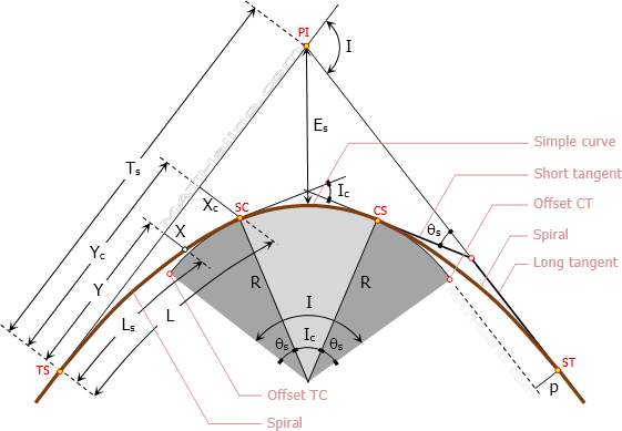
Spiral Curve

Spirals are used to overcome the abrupt change in curvature and superelevation that occurs between tangent and circular curve. The spiral curve is used to gradually change the curvature and superelevation of the road, thus called transition curve.
 

003-spiral-curve-transition-curve.gif

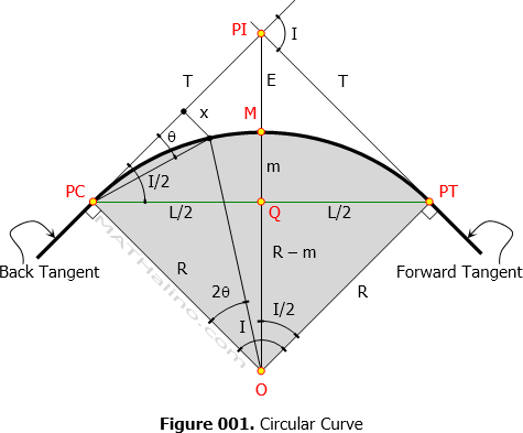
Simple Curves

Formulas for Circular Curves
The formulas we are about to present need not be memorized. All we need is geometry plus names of all elements in simple curve. Note that we are only dealing with circular arc, it is in our great advantage if we deal it at geometry level rather than memorize these formulas.

001-circular-simple-curve.gif


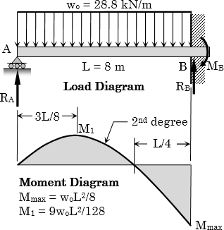
Example 03: Finding the Number of 32-mm Steel Bars for Doubly-Reinforced Concrete Propped Beam

Problem
A propped beam 8 m long is to support a total load of 28.8 kN/m. It is desired to find the steel reinforcements at the most critical section in bending. The cross section of the concrete beam is 400 mm by 600 mm with an effective cover of 60 mm for the reinforcements. f’c = 21 MPa, fs = 140 MPa, n = 9. Determine the required number of 32 mm ø tension bars and the required number of 32 mm ø compression bars.
 

wsd-example-03-propped-beam.jpg


Example 02: Finding the Number of 28-mm Steel Bars of Singly-Reinforced Concrete Cantilever Beam

Problem
A reinforced concrete cantilever beam 4 m long has a cross-sectional dimensions of 400 mm by 750 mm. The steel reinforcement has an effective depth of 685 mm. The beam is to support a superimposed load of 29.05 kN/m including its own weight. Use f’c = 21 MPa, fs = 165 MPa, and n = 9. Determine the required number of 28 mm ø reinforcing bars using Working Stress Design method.
 

wsd-example-02-cantilever-beam.jpg


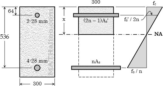
Example 04: Stress of Tension Steel, Stress of Compression Steel, and Stress of Concrete in Doubly Reinforced Beam

Problem
A 300 mm × 600 mm reinforced concrete beam section is reinforced with 4 - 28-mm-diameter tension steel at d = 536 mm and 2 - 28-mm-diameter compression steel at d' = 64 mm. The section is subjected to a bending moment of 150 kN·m. Use n = 9.

1. Find the maximum stress in concrete.
2. Determine the stress in the compression steel.
3. Calculate the stress in the tension steel.
 

wsd-example-04-doubly-reinforced-beam-analysis.jpg

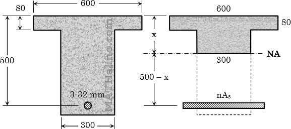
Example 03: Compressive Force at the Section of Concrete T-Beam

Problem
The following are the dimensions of a concrete T-beam section

Width of flange, bf = 600 mm
Thickness of flange, tf = 80 mm
Width of web, bw = 300 mm
Effective depth, d = 500 mm

The beam is reinforced with 3-32 mm diameter bars in tension and is carrying a moment of 100 kN·m. Find the total compressive force in the concrete. Use n = 9.
 

wsd-example-03-strength-of-t-beam.jpg


Example 01: Total Compression Force at the Section of Concrete Beam

Problem
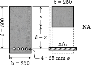
A rectangular reinforced concrete beam with width of 250 mm and effective depth of 500 mm is subjected to 150 kN·m bending moment. The beam is reinforced with 4 – 25 mm ø bars. Use alternate design method and modular ratio n = 9.

  1. What is the maximum stress of concrete?
  2. What is the maximum stress of steel?
  3. What is the total compressive force in concrete?


wsd-example-01-flexural-stresses-concrete-steel.jpg


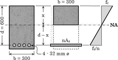
Example 01: Required Steel Area of Reinforced Concrete Beam

Problem
A rectangular concrete beam is reinforced in tension only. The width is 300 mm and the effective depth is 600 mm. The beam carries a moment of 80 kN·m which causes a stress of 5 MPa in the extreme compression fiber of concrete. Use n = 9.
1.   What is the distance of the neutral axis from the top of the beam?
2.   Calculate the required area for steel reinforcement.
3.   Find the stress developed in the steel.
 

wsd-example-01-unknown-steel-area.jpg