Derivation of formula for volume of a frustum of pyramid/cone
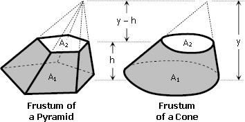
Frustum of a pyramid and frustum of a cone
The formula for frustum of a pyramid or frustum of a cone is given by
$V = \dfrac{h}{3} \left[ \, A_1 + A_2 + \sqrt{A_1A_2} \, \right]$
Where:
h = perpendicular distance between A1 and A2 (h is called the altitude of the frustum)
A1 = area of the lower base
A2 = area of the upper base
Note that A1 and A2 are parallel to each other.
 The vertical shear at C in the figure shown in
Recent comments
is it not…