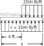
$w = 30(1000)/12$
$w = 2500 \, \text{lb/ft}$
$\Sigma F_V = 0$
$R = W$
$20r = 30(1000)$
$r = 1500 \, \text{lb/ft}$
 First segment (from 0 to 4 ft from left):
$V_1 = 1500x$
$M_1 = 1500x(x/2)$
$M_1 = 750x^2$
 Second segment (from 4 ft to mid-span):
$V_2 = 1500x - 2500(x - 4)$
$V_2 = 10000 - 1000x$
$M_2 = 1500x(x/2) - 2500(x - 4)(x - 4)/2$
$M_2 = 750x^2 - 1250(x - 4)^2$
 To draw the Shear Diagram:
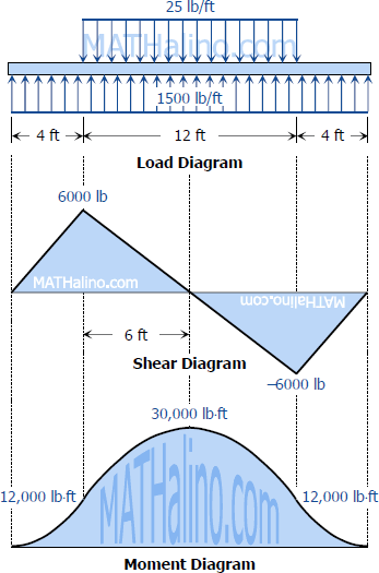
- For the first segment, V1 = 1500x is linear; at x = 0, V1 = 0; at x = 4 ft, V1 = 6000 lb.
- For the second segment, V2 = 10000 - 1000x is also linear; at x = 4 ft, V1 = 6000 lb; at mid-span, x = 10 ft, V1 = 0.
- For the next half of the beam, the shear diagram can be accomplished by the concept of symmetry.
To draw the Moment Diagram:
- For the first segment, M1 = 750x2 is a second degree curve, an open upward parabola; at x = 0, M1 = 0; at x = 4 ft, M1 = 12000 lb·ft.
- For the second segment, M2 = 750x2 - 1250(x - 4)2 is a second degree curve, an downward parabola; at x = 4 ft, M2 = 12000 lb·ft; at mid-span, x = 10 ft, M2 = 30000 lb·ft.
- The next half of the diagram, from x = 10 ft to x = 20 ft, can be drawn by using the concept of symmetry.
