Solution to Problem 128 Bearing Stress
Problem 128
- Read more about Solution to Problem 128 Bearing Stress
- Log in or register to post comments
Problem 128
Problem 127
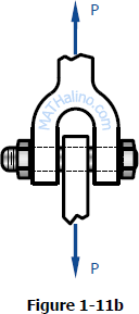
In the clevis shown in Fig. 1-11b, find the minimum bolt diameter and the minimum thickness of each yoke that will support a load P = 14 kips without exceeding a shearing stress of 12 ksi and a bearing stress of 20 ksi.

Problem 126
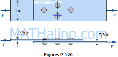
The lap joint shown in Fig. P-126 is fastened by four ¾-in.-diameter rivets. Calculate the maximum safe load P that can be applied if the shearing stress in the rivets is limited to 14 ksi and the bearing stress in the plates is limited to 18 ksi. Assume the applied load is uniformly distributed among the four rivets.

In Fig. 1-12, assume that a 20-mm-diameter rivet joins the plates that are each 110 mm wide. The allowable stresses are 120 MPa for bearing in the plate material and 60 MPa for shearing of rivet. Determine (a) the minimum thickness of each plate; and (b) the largest average tensile stress in the plates.
Problem 123
A rectangular piece of wood, 50 mm by 100 mm in cross section, is used as a compression block shown in Fig. P-123. Determine the axial force P that can be safely applied to the block if the compressive stress in wood is limited to 20 MN/m2 and the shearing stress parallel to the grain is limited to 5MN/m2. The grain makes an angle of 20° with the horizontal, as shown. (Hint: Use the results in Problem 122.)
Problem 121
Referring to Fig. P-121, compute the maximum force P that can be applied by the machine operator, if the shearing stress in the pin at B and the axial stress in the control rod at C are limited to 4000 psi and 5000 psi, respectively. The diameters are 0.25 inch for the pin, and 0.5 inch for the control rod. Assume single shear for the pin at B.
Problem 120
The members of the structure in Fig. P-120 weigh 200 lb/ft. Determine the smallest diameter pin that can be used at A if the shearing stress is limited to 5000 psi. Assume single shear.
Problem 119
Compute the shearing stress in the pin at B for the member supported as shown in Fig. P-119. The pin diameter is 20 mm.
Problem 118
A 200-mm-diameter pulley is prevented from rotating relative to 60-mm-diameter shaft by a 70-mm-long key, as shown in Fig. P-118. If a torque T = 2.2 kN·m is applied to the shaft, determine the width b if the allowable shearing stress in the key is 60 MPa.
Recent comments