The Moment Distribution Method
Moment distribution is based on the method of successive approximation developed by Hardy Cross (1885–1959) in his stay at the University of Illinois at Urbana-Champaign (UIUC). This method is applicable to all types of rigid frame analysis.
Carry-Over Moment
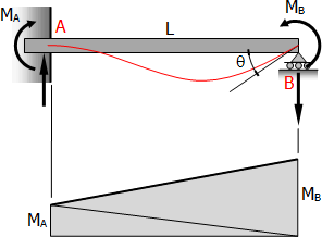
Carry-over moment is defined as the moment induced at the fixed end of a beam by the action of the moment applied at the other end.

Consider the propped beam shown above,
$EI\,t_{B/A} = (\text{Area}_{AB}) \cdot \bar{X}_B = 0$
$\frac{1}{2}LM_A(\frac{2}{3}L) + \frac{1}{2}LM_B(\frac{1}{3}L) = 0$
Thus, the moment applied at the roller end carries over to the fixed end a moment that is half the amount and of opposite sign.
Beam Stiffness
Beam stiffness is the moment required to produce unit rotation at the simply supported end of a beam, the other end being rigidly fixed.
From the beam above,
$EI\,\theta_{AB} = \text{Area}_{AB}$
$EI\,\theta = \frac{1}{2}LM_A + \frac{1}{2}LM_B$
$EI\,\theta = \frac{1}{2}L(-\frac{1}{2}M_B) + \frac{1}{2}LM_B$
$EI\,\theta = -\frac{1}{4}LM_B + \frac{1}{2}LM_B$
$EI\,\theta = \frac{1}{4}LM_B$
$M_B = \dfrac{4EI\,\theta}{L}$
If θ = 1 radian, MB = beam stiffness K, thus
For constant E,
Modified K
For hinge and roller ends, multiply K by 3/4 to eliminate further distribution of moment on that support.
Fixed End Moments (FEM)
Assume that each span of continuous beam to be fully restrained against rotation then fixed-end moments at the ends its members are computed.
Sign Convention
Counterclockwise moments acting on the beam are considered to be positive, and clockwise moments acting on the beam are considered negative. This implies that clockwise reaction at the joint is positive and counterclockwise reaction at the joint is negative.
| Type of Load | End Moments (Actual Sign) |
End Moments (Used Sign) |
 |
$M_A = -\dfrac{Pab^2}{L^2}$
$M_B = -\dfrac{Pa^2b}{L^2}$ |
$FEM_{AB} = -\dfrac{Pab^2}{L^2}$
$FEM_{BA} = +\dfrac{Pa^2b}{L^2}$ |
 |
$M_A = -\dfrac{PL}{8}$
$M_B = -\dfrac{PL}{8}$ |
$FEM_{AB} = -\dfrac{PL}{8}$
$FEM_{BA} = +\dfrac{PL}{8}$ |
 |
$M_A = -\dfrac{w_oL^2}{12}$
$M_B = -\dfrac{w_oL^2}{12}$ |
$FEM_{AB} = -\dfrac{w_oL^2}{12}$
$FEM_{BA} = +\dfrac{w_oL^2}{12}$ |
 |
$M_A = -\dfrac{5w_oL^2}{192}$
$M_B = -\dfrac{11w_oL^2}{192}$ |
$FEM_{AB} = -\dfrac{5w_oL^2}{192}$
$FEM_{BA} = +\dfrac{11w_oL^2}{192}$ |
 |
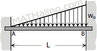
$M_A = -\dfrac{w_oL^2}{30}$
$M_B = -\dfrac{w_oL^2}{20}$ |
$FEM_{AB} = -\dfrac{w_oL^2}{30}$
$FEM_{BA} = +\dfrac{w_oL^2}{20}$ |
 |
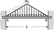
$M_A = -\dfrac{5w_oL^2}{96}$
$M_B = -\dfrac{5w_oL^2}{96}$ |
$FEM_{AB} = -\dfrac{5w_oL^2}{96}$
$FEM_{BA} = +\dfrac{5w_oL^2}{96}$ |
 |
$M_A = \dfrac{Mb}{L}\left( \dfrac{3a}{L} - 1 \right)$
$M_B = -\dfrac{Ma}{L}\left( \dfrac{3b}{L} - 1 \right)$ |
$FEM_{AB} = +\dfrac{Mb}{L}\left( \dfrac{3a}{L} - 1 \right)$
$FEM_{BA} = +\dfrac{Ma}{L}\left( \dfrac{3b}{L} - 1 \right)$ |
 |
$M_A = -\dfrac{6EI \Delta}{L^2}$
$M_B = \dfrac{6EI \Delta}{L^2}$ |
$FEM_{AB} = -\dfrac{6EI \Delta}{L^2}$
$FEM_{BA} = -\dfrac{6EI \Delta}{L^2}$ |
Distribution Factor, DF
At a joint, the distribution factor of a member is the ratio of the bending stiffness of the member to the sum of bending stiffness of all the members connected to the joint.
In general, the end moments of any two adjacent spans are not equal creating an unbalanced moment at the joint. This unbalanced moment is then distributed in percentage equal to the distribution factor.
Note:
DF = 0 for fixed end.
DF = 1 for hinged or roller end.
