Mechanics of Reinforced Concrete in Flexure
Assume a prismatic, homogeneous, simply supported concrete beam. The beam is then superimposed with a uniformly distributed load. By our understanding of simple mechanics, there will be a maximum moment at the midspan, and concurrently, zero shear. We can also say that the beam will start to deflect and bend due to the superimposed load and its own self-weight. Considering a section at midspan, we can dissolve the internal moment as a couple and observe that there will be two axial forces acting on the beam’s cross-section: one on top in compression and another one at the bottom in tension. In actuality, the internal moment is not reduced to two forces only. Instead, its compressive stress is distributed variably across the beam's cross-section from the neutral axis.
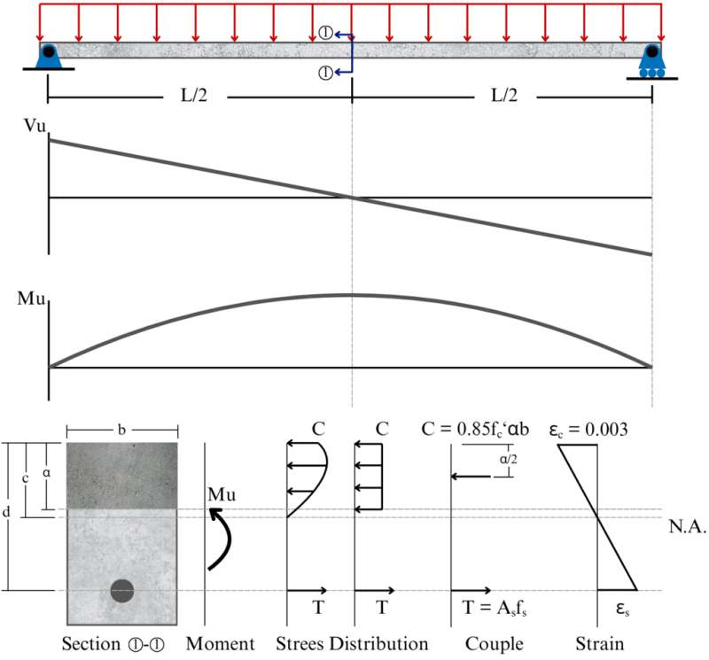
Concrete is strong in compression but weak in tension. NSCP 2015 allows us to estimate the rupture strength (tensile strength) of concrete to be \(f_t=0.42\lambda\sqrt{f'_c}\). That is about 6% to 8% of the concrete’s compressive strength. Although concrete does have tensile strength, in practice, we ignore it and let the reinforcement carry all of the tensile stress. To simplify the analysis further, we also assume a uniformly distributed compression zone. To conform with NSCP 2015 Section 422.2.2.4.1, the effective concrete stress to be used shall be \(0.85f'_c\). As such, we can simplify the stress distribution diagram as shown in the figure. The bounding area of the compression zone is defined as the beam width multiplied by α. Variable α is the depth of the compression zone \(\alpha=\beta_1c\), where:
- \( c \) is the distance from the neutral axis of the beam to the outermost compression fiber.
- \(\beta_1\) is a piecewise function that factors the depth of the compression zone being considered in terms of \(f'_c\).
\[ \begin{array}{lll}
\beta_1=0.85 & ~ & \text{if } 17\text{ MPa}\le f'_c\le 28 \text{ MPa} \\
\beta_1=0.85-0.05\cdot\dfrac{f'_c-28}{7} & ~ & \text{if } 28\text{ MPa}\lt f'_c\lt 55\text{ MPa} \\
\beta_1=0.65 & ~ & \text{if } f'_c\ge 55\text{ MPa}
\end{array} \]
Analysis of Singly Reinforced Beam
Given:
\( b \) = width of beam
\( h \) = total beam depth
\(Ø_b\) = diameter of reinforcing bars
\(Ø_s\) = diameter of stirrups
\(f'_c\) = concrete compressive strength
\(f_y\) = steel yield strength
cc = concrete cover (typically 40 mm for beams)
\( n \) = number of bars in tension
Step 1: Solve for other section properties
- \(A_s=\dfrac{n\piØ_b^2}{4}\), cross-secitonal area of steel reinforcement in tension
- \(d=h-cc-Ø_s-Ø_b/2\) (for single layer), effective depth; centroidal position of tensile reinforcement measured perpendicular from the outermost compression fiber
- \(d_t\), centroidal position of the extreme reinforcement measured perpendicular from the outermost compression fiber
- \(\beta_1\)
Step 2: C = T, then solve for α
C and T are the couple forces due to bending. To determine the forces, we simply multiply the material's stress by its area
\( \begin{array}{llll}
\quad & C=0.85f'_c \times αb & ~ & \text{Compression force carried by the compression zone.} \\
\quad & T=f_y \times A_s & ~ & \text{Tensile force carried by the reinforcement.}
\end{array} \)
\[\boxed{0.85f'_cαb=f_yA_s}\]
Then solve for the depth of compression zone, α
\[\boxed{α=\dfrac{f_yA_s}{0.85f'_cb}}\]
Step 3: Solve for \(f_s\)
In Step 2, it is important to note that \(f_y\) in the solution for α is an assumption. Using \(f_y\) in the solution means the steel reinforcement will yield (i.e., reach its maximum stress before permanent deformation). However, we do not yet know if the reinforcement will yield. Therefore, we have to check whether or not this assumption is true by solving for \(f_s\).
\(f_s\) is the actual stress that the steel will experience. One avenue to solve for \(f_s\) is to determine the reinforcement strain, \(ε_s\). NSCP 2015 Section 422.2.2.1 allows us to assume that, in flexure, concrete fails in compression, and the limiting strain in the outermost compression fiber is 0.003. Strain at the neutral axis is zero; thus, we can derive the reinforcing strain as follows:
\(\dfrac{0.003}{c}=\dfrac{0.003+ε_s}{d}\)
\(ε_s=\dfrac{0.003d}{c}-0.003\)
\(ε_s=0.003\left(\dfrac{d}{c}-1\right)=0.003\left(\dfrac{d-c}{c}\right)\)
Using \(α=\beta_1c\),
\(ε_s=0.003\left(\dfrac{\beta_1d}{α}-1\right)=0.003\left(\dfrac{\beta_1d-α}{α}\right)\)
The modulus of elasticity for steel is E = 200, 000 MPa, and by virtue of Hooke's Law, we can now solve for \(f_s\) in terms of \(ε_s\)
\(σ=Eε\)
\(f_s=Eε_s\)
\(f_s=200,000 \times 0.003\left(\dfrac{\beta_1d-α}{α}\right)\)
\[\boxed{f_s=600\left(\dfrac{\beta_1d-α}{α}\right)}\]
The following cases conform to NSCP 2015 Section 420.2.2.1
- If \(f_y\ge f_s\), steel will yield, then the assumption to use \(f_y\) in Step 2 is correct. Proceed to Step 4 using \(f_s=f_y\)
- If \(f_s\lt f_y\), steel will not yield, then the assumption to use \(f_y\) in Step 2 is incorrect. In this case, resolve for α, this time using \(f_s\) in the solution of C = T
\(0.85f'_cαb=A_sf_s\)
\(0.85f'_cαb=A_s(600)\left(\dfrac{\beta_1d-α}{α}\right)\)
Then, solve for the new α, solve for the new \(f_s\), and proceed to Step 4.
Step 4: Solve for \(ε_t\)
\(ε_t\) is the tensile strain of the extreme tension reinforcement (layer of reinforcement that is furthest from the neutral axis). It can be solved using the equation derived previously. Except this time, we use \(d_t\) instead of \(d\). For single-layer reinforcement, \(d\) is equal to \(d_t\).
\[\boxed{ε_t=0.003\left(\dfrac{\beta_1 d_t-α}{α}\right)}\]
\(ε_t\) helps to determine if the beam is tension-controlled, in transition, or compression-controlled by comparing it to the following:
\[ \begin{array}{lll}
\vcenter{{\small \bullet}} ~ \text{ If } ε_t \le ε_y & ~ & \text{Compression-Controlled Section} \\
\vcenter{{\small \bullet}} ~ \text{ If } ε_y \lt ε_t\lt 0.005 & ~ & \text{Transition Zone Section} \\
\vcenter{{\small \bullet}} ~ \text{ If } ε_t \ge 0.005 & ~ & \text{Tension-Controlled Seciton}
\end{array} \]
Where \(ε_y\) is the yield strain of the steel reinforcement. For example, with Grade 60 reinforcement (fy = 414 MPa), the yield strain of this material can be determined by using Hooke’s Law.
\(σ=Eε\)
\(f_y=Eε_y\)
\(ε_y=\dfrac{f_y}{E}=\dfrac{414}{200, 000}=0.00207\)
Therefore, the beam is characterized as compression-controlled if the reinforcement strain does not reach its yield strain, and as tension-controlled if it reaches 0.005 or greater. Anything in between is considered to be in transition. We chose the parameter strain to assess the beam's characteristics rather than stress because the reinforcement's stress alone does not provide sufficient information to determine it. There will be cases in the transition zone where the steel will yield, but its strain will not yet reach 0.005.
Step 5: Solve for \(\phi\)
The following flexural reduction factors for beams conform to NSCP 2015 Section 421.2.1 and Table 421.2.2 for non-spiral type of transverse reinforcement.
\( \begin{array}{lll}
\vcenter{{\small \bullet}} ~ \phi=0.90 & ~ & \text{if Tension-Controlled} \\
\vcenter{{\small \bullet}} ~ \phi=0.65+0.25\dfrac{ε_t-ε_y}{0.005-ε_y} & ~ & \text{if in Transition Zone} \\
\vcenter{{\small \bullet}} ~ \phi=0.65 & ~ & \text{if Compression-Controlled}
\end{array} \)
Step 6: Solve for Mn or \(\phi\)Mn
As illustrated in the first figure, the bending moment in the beam can be represented as an equivalent internal couple. To determine the beam's moment capacity, this concept is applied in reverse. The moment capacity is obtained by multiplying the axial force capacity of the material (either the concrete in compression or the steel in tension) by the corresponding lever arm between the forces. We can choose the axial force to be concrete or steel, because, remember, in Step 1, we already defined them as equal: C = T. Therefore, the nominal moment capacity is expressed as Force × Distance or:
\[ \begin{array}{c}
\boxed{\text{Mn}=0.85f'_c αb \left( d-\dfrac{α}{2} \right) } \\
\boxed{\text{Mn}=f_s A_s \left( d-\dfrac{α}{2} \right) }
\end{array} \]
And to determine the design moment capacity, simply multiply the nominal moment capacity, Mn, by the reduction factor, \(\phi\) solved in the previous step.
Problem 1
A 6 m, 400×650 mm rectangular simply-supported concrete beam is superimposed with 25 kN/m dead load and 16 kN/m live load. The beam is also made to carry a 12 kN dead load and 24 kN live load at midspan. The beam is reinforced with 6-Ø25 mm reinforcement and \(Ø_s\) = 10 mm for stirrups. Grade 60 (fy = 414 MPa) bars and concrete compressive strength of 35 MPa are used in the construction of this beam. Unit weight of concrete is γc = 23.5 kN/m\(^3\). Determine the design moment capacity of the beam. Is the beam adequate to carry the loads? Use 1.2D + 1.6L

Wow! :>
Wow! :>