Energy and Head of Flow
Kinetic Energy and Potential Energy
Energy is defined as ability to do work. Both energy and work are measured in Newton-meter (or pounds-foot in English). Kinetic energy and potential energy are the two commonly recognized forms of energy. In a flowing fluid, potential energy may in turn be subdivided into energy due to position or elevation above a given datum, and energy due to pressure in the fluid. Head is the amount of energy per Newton (or per pound) of fluid.
Kinetic Energy and Velocity Head
Kinetic energy is the ability of a mass to do work by virtue of its velocity. The kinetic energy of a mass m having a velocity v is ½mv2. Since m = W/g,
$\text{Velocity head} = \dfrac{K.E.}{W} = \dfrac{v^2}{2g}$
Velocity Head of Circular Pipes
The velocity head of circular pipe of diameter D flowing full can be found as follows.
$\dfrac{v^2}{2g} = \dfrac{(Q/A)^2}{2g} = \dfrac{Q^2}{2gA^2}$
$\dfrac{v^2}{2g} = \dfrac{Q^2}{2g(\frac{1}{4}\pi D^2)^2} = \dfrac{16Q^2}{2g(\pi^2 D^4}$
Elevation Energy and Elevation Head
In connection to the action of gravity, elevation energy is manifested in a fluid by virtue of its position or elevation with respect to a horizontal datum plane.
$\text{Elevation head} = \dfrac{\text{Elevation energy}}{W} = z$
Pressure Energy and Pressure Head
A mass of fluid acquires pressure energy when it is in contact with other masses having some form of energy. Pressure energy therefore is an energy transmitted to the fluid by another mass that possesses some energy.
$\text{Pressure head} = \dfrac{\text{Pressure energy}}{W} = \dfrac{p}{\gamma}$
Back to top
Total Energy of Flow
The total energy or head in a fluid is the sum of kinetic and potential energies. Recall that potential energies are pressure energy and elevation energy.
Total head = Velocity head + Pressure head + Elevation head
In symbol, the total head energy is
Where:
v = mean velocity of flow (m/sec in SI and ft/sec in English)
p = fluid pressure (N/m2 or Pa in SI and lb/ft2 or psf in English)
z = position of fluid above or below the datum plane (m in SI and ft in English)
g = gravitational acceleration (9.81 m/sec2 in SI and 32.2 ft/sec2 in English)
γ = Unit weight of fluid (N/m3 in SI and lb/ft3 in English)
Power and Efficiency
Power is the rate of doing work per unit of time. For a fluid of unit weight γ (N/m3) flowing at the rate of Q (m3/sec) with a total energy of E (m), the power (Watt) is
$\text{Efficiency} = \dfrac{\text{Output}}{\text{Input}} \times 100\%$
Note:
1 horsepower (hp) = 746 Watts
1 horsepower (hp) = 550 ft-lb/sec
1 Watt = 1 N-m/sec = 1 Joule/sec
Bernoulli’s Energy Theorem

Daniel Bernoulli
(1700 - 1782)
Applying the law of conservation of energy to fluids that may be considered incompressible, Bernoulli’s theorem may be stated as follows:
Neglecting head lost, the total amount of energy per unit weight is constant at any point in the path of flow.
Bernoulli's Energy Equations
Energy Equation Neglecting Head Loss
Without head losses, the total energy at point (1) is equal to the total energy at point (2). No head lost is an ideal condition leading to theoretical values in the results.
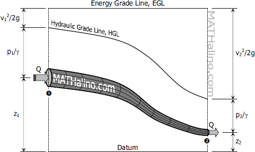
$\dfrac{{v_1}^2}{2g} + \dfrac{p_1}{\gamma} + z_1 = \dfrac{{v_2}^2}{2g} + \dfrac{p_2}{\gamma} + z_2$
Energy Equation Considering Head Loss
The actual values can be found by considering head losses in the computation of flow energy.
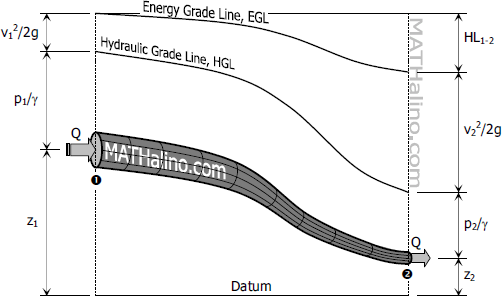
$\dfrac{{v_1}^2}{2g} + \dfrac{p_1}{\gamma} + z_1 - HL_{1-2} = \dfrac{{v_2}^2}{2g} + \dfrac{p_2}{\gamma} + z_2$
Energy Equation with Pump
In most cases, pump is used to raise water from lower elevation to higher elevation. In a more technical term, the use of pump is basically to increase the energy of flow. The pump consumes electrical energy (Pinput) and delivers flow energy (Poutput).
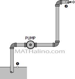
$\dfrac{{v_1}^2}{2g} + \dfrac{p_1}{\gamma} + z_1 + {HA} - HL_{1-2} = \dfrac{{v_2}^2}{2g} + \dfrac{p_2}{\gamma} + z_2$
$\text{Output power of pump} = Q \gamma {HA}$
Energy Equation with Turbine
Turbines extract flow energy and converted it into mechanical energy which in turn converted into electrical energy.
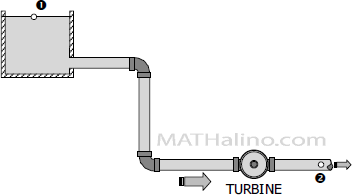
$\dfrac{{v_1}^2}{2g} + \dfrac{p_1}{\gamma} + z_1 - {HE} - HL_{1-2} = \dfrac{{v_2}^2}{2g} + \dfrac{p_2}{\gamma} + z_2$
$\text{Input power of turbine} = Q \gamma {HE}$
Back to top
Hydraulic and Energy Grade Lines
Hydraulic Grade Line (HGL)
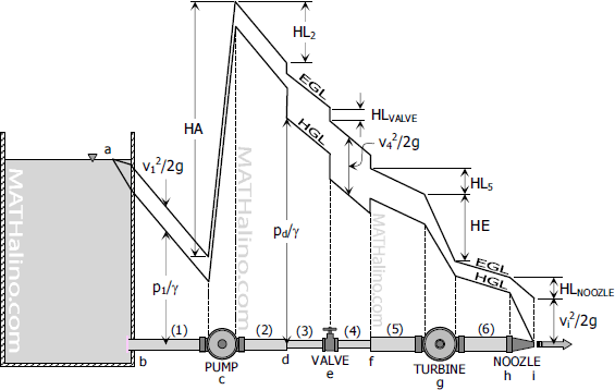
Hydraulic grade line, also called hydraulic gradient and pressure gradient, is the graphical representation of the potential head (pressure head + elevation head). It is the line to which liquid rises in successive piezometer tubes. The line is always at a distance (p/γ + z) above the datum plane.
- HGL slopes downward in the direction of flow but it may rise or fall due to change in pressure.
- HGL is parallel to EGL for uniform pipe cross section.
- For horizontal pipes with constant cross section, the drop in pressure gradient between two points is equivalent to the head lost between these points.
Energy Grade Line (EGL)
Energy grade line is always above the hydraulic grade line by an amount equal to the velocity head. Thus, the distance of energy gradient above the datum plane is always (v2/2g + p/γ + z). Energy grade line therefore is the graphical representation of the total energy of flow.
- EGL slopes downward in the direction of flow and will only rise with the presence of pump.
- The vertical drop of EGL between two points is the head lost between those points.
- EGL is parallel to HGL for uniform pipe cross section.
- EGL is always above the HGL by v2/2g.
- Neglecting head loss, EGL is horizontal.
Illustration showing the behavior of EGL and HGL
