Problem 407 Cantilever Truss - Method of Joints
Problem 407
In the cantilever truss shown in Fig. P-407, compute the force in members AB, BE, and DE.
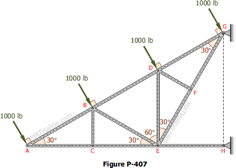
Problem 407
In the cantilever truss shown in Fig. P-407, compute the force in members AB, BE, and DE.

Problem 406
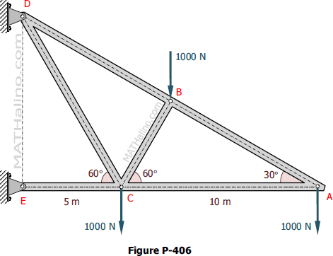
The cantilever truss in Fig. P-406 is hinged at D and E. Find the force in each member.
Problem 405
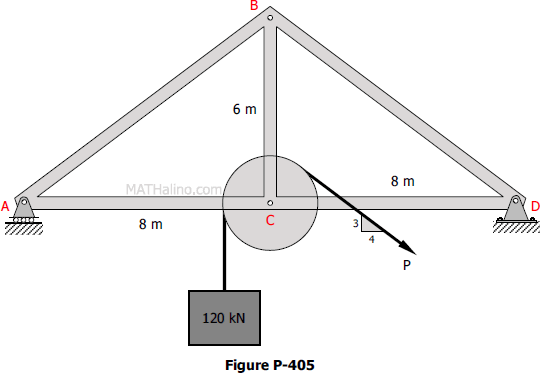
Determine the force in each bar of the truss shown in Fig. P-405 caused by lifting the 120 kN load at a constant velocity of 8 m per sec. What change in these forces, if any, results from placing the roller support at D and the hinge support at A?
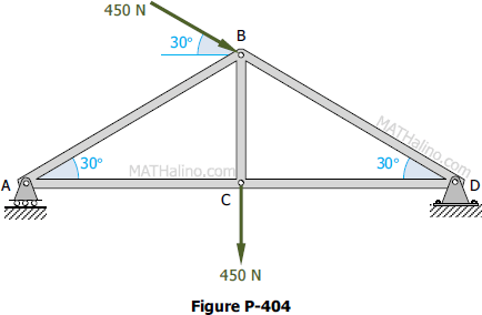
Problem 404
Determine the forces in the members of the roof truss shown in Fig. P-404.
Problem 005-mj
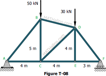
Compute the force in all members of the truss shown in Fig. T-08.
Problem 004-mj
The truss pinned to the floor at D, and supported by a roller at point A is loaded as shown in Fig. T-06. Determine the force in member CG.

Problem 003-mj
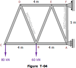
Find the force in each member of the truss shown in Fig. T-04.
Problem 002-mj
The structure in Fig. T-02 is a truss which is pinned to the floor at point A, and supported by a roller at point D. Determine the force to all members of the truss.

Problem 403
Determine the force in each bar of the truss shown in Fig. P-403.

Problem
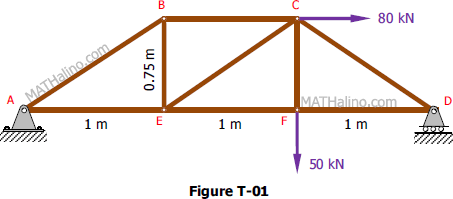
Find the force acting in all members of the truss shown in Figure T-01.
