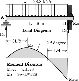
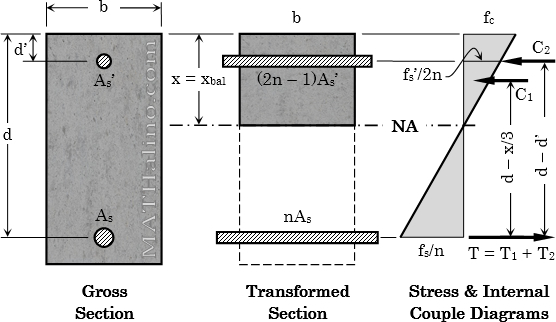
Example 03: Finding the Number of 32-mm Steel Bars for Doubly-Reinforced Concrete Propped Beam

Problem
A propped beam 8 m long is to support a total load of 28.8 kN/m. It is desired to find the steel reinforcements at the most critical section in bending. The cross section of the concrete beam is 400 mm by 600 mm with an effective cover of 60 mm for the reinforcements. f’c = 21 MPa, fs = 140 MPa, n = 9. Determine the required number of 32 mm ø tension bars and the required number of 32 mm ø compression bars.
 

wsd-example-03-propped-beam.jpg


Example 02: Finding the Number of 28-mm Steel Bars of Singly-Reinforced Concrete Cantilever Beam

Problem
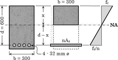
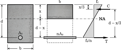
A reinforced concrete cantilever beam 4 m long has a cross-sectional dimensions of 400 mm by 750 mm. The steel reinforcement has an effective depth of 685 mm. The beam is to support a superimposed load of 29.05 kN/m including its own weight. Use f’c = 21 MPa, fs = 165 MPa, and n = 9. Determine the required number of 28 mm ø reinforcing bars using Working Stress Design method.
 

wsd-example-02-cantilever-beam.jpg


Example 01: Total Compression Force at the Section of Concrete Beam

Problem
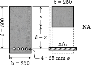
A rectangular reinforced concrete beam with width of 250 mm and effective depth of 500 mm is subjected to 150 kN·m bending moment. The beam is reinforced with 4 – 25 mm ø bars. Use alternate design method and modular ratio n = 9.

  1. What is the maximum stress of concrete?
  2. What is the maximum stress of steel?
  3. What is the total compressive force in concrete?


wsd-example-01-flexural-stresses-concrete-steel.jpg


Example 01: Required Steel Area of Reinforced Concrete Beam

Problem
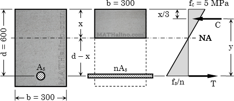
A rectangular concrete beam is reinforced in tension only. The width is 300 mm and the effective depth is 600 mm. The beam carries a moment of 80 kN·m which causes a stress of 5 MPa in the extreme compression fiber of concrete. Use n = 9.
1.   What is the distance of the neutral axis from the top of the beam?
2.   Calculate the required area for steel reinforcement.
3.   Find the stress developed in the steel.
 

wsd-example-01-unknown-steel-area.jpg


Design of Steel Reinforcement of Concrete Beams by WSD Method

Steps is for finding the required steel reinforcements of beam with known Mmax and other beam properties using Working Stress Design method.

Given the following, direct or indirect:

Width or breadth = b
Effective depth = d
Allowable stress for concrete = fc
Allowable stress for steel = fs
Modular ratio = n
Maximum moment carried by the beam = Mmax


wsd-doubly-reinforced-beam.jpg

Working Stress Design of Reinforced Concrete

Working Stress Design is called Alternate Design Method by NSCP (National Structural Code of the Philippines) and ACI (American Concrete Institute, ACI).
 

Code Reference
NSCP 2010 - Section 424: Alternate Design Method
ACI 318 - Appendix A: Alternate Design Method
 

Notation

fc = allowable compressive stress of concrete
fs = allowable tesnile stress of steel reinforcement
f'c = specified compressive strength of concrete
fy = specified yield strength of steel reinforcement
Ec = modulus of elasticity of concrete
Es = modulus of elasticity of steel
n = modular ratio
M = design moment
d = distance from extreme concrete fiber to centroid of steel reinforcement
kd = distance from the neutral axis to the extreme fiber of concrete
jd = distance between compressive force C and tensile force T
ρ = ratio of the area of steel to the effective area of concrete
As = area of steel reinforcement


wsd-assumptions.jpg