001 Solid steel ball remolded into hollow steel ball
Problem 001
A 523.6 cm3 solid spherical steel ball was melted and remolded into a hollow steel ball so that the hollow diameter is equal to the diameter of the original steel ball. Find the thickness of the hollow steel ball.
- Read more about 001 Solid steel ball remolded into hollow steel ball
- Log in or register to post comments
Solution to Problem 505 | Flexure Formula
Problem 505
A high strength steel band saw, 20 mm wide by 0.80 mm thick, runs over pulleys 600 mm in diameter. What maximum flexural stress is developed? What minimum diameter pulleys can be used without exceeding a flexural stress of 400 MPa? Assume E = 200 GPa.
- Read more about Solution to Problem 505 | Flexure Formula
- Log in or register to post comments
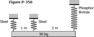
Solution to Problem 350 | Helical Springs
Problem 350
As shown in Fig. P-350, a homogeneous 50-kg rigid block is suspended by the three springs whose lower ends were originally at the same level. Each steel spring has 24 turns of 10-mm-diameter on a mean diameter of 100 mm, and G = 83 GPa. The bronze spring has 48 turns of 20-mm-diameter wire on a mean diameter of 150 mm, and G = 42 GPa. Compute the maximum shearing stress in each spring using Eq. (3-9).

- Read more about Solution to Problem 350 | Helical Springs
- Log in or register to post comments
Solution to Problem 320 Torsion
Problem 320
In Prob. 319, determine the ratio of lengths b/a so that each material will be stressed to its permissible limit. What torque T is required?
- Read more about Solution to Problem 320 Torsion
- 2 comments
- Log in or register to post comments
Solution to Problem 319 Torsion
Problem 319
The compound shaft shown in Fig. P-319 is attached to rigid supports. For the bronze segment AB, the diameter is 75 mm, τ ≤ 60 MPa, and G = 35 GPa. For the steel segment BC, the diameter is 50 mm, τ ≤ 80 MPa, and G = 83 GPa. If a = 2 m and b = 1.5 m, compute the maximum torque T that can be applied.
- Read more about Solution to Problem 319 Torsion
- Log in or register to post comments
Solution to Problem 276 Thermal Stress
Problem 276
Four steel bars jointly support a mass of 15 Mg as shown in Fig. P-276. Each bar has a cross-sectional area of 600 mm2. Find the load carried by each bar after a temperature rise of 50°C. Assume α = 11.7 µm/(m·°C) and E = 200 GPa.
- Read more about Solution to Problem 276 Thermal Stress
- Log in or register to post comments
Solution to Problem 275 Thermal Stress
Problem 275
A rigid horizontal bar of negligible mass is connected to two rods as shown in Fig. P-275. If the system is initially stress-free. Calculate the temperature change that will cause a tensile stress of 90 MPa in the brass rod. Assume that both rods are subjected to the change in temperature.
- Read more about Solution to Problem 275 Thermal Stress
- Log in or register to post comments
Solution to Problem 274 Thermal Stress
Problem 274
At what temperature will the aluminum and steel segments in Prob. 273 have numerically equal stress?
- Read more about Solution to Problem 274 Thermal Stress
- Log in or register to post comments
Solution to Problem 273 Thermal Stress
Problem 273
The composite bar shown in Fig. P-273 is firmly attached to unyielding supports. An axial force P = 50 kips is applied at 60°F. Compute the stress in each material at 120°F. Assume α = 6.5 × 10⁻⁶ in/(in·°F) for steel and 12.8 × 10⁻⁶ in/(in·°F) for aluminum.

- Read more about Solution to Problem 273 Thermal Stress
- Log in or register to post comments
Solution to Problem 272 Thermal Stress
Problem 272
For the assembly in Fig. 271, find the stress in each rod if the temperature rises 30°C after a load W = 120 kN is applied.
- Read more about Solution to Problem 272 Thermal Stress
- Log in or register to post comments
