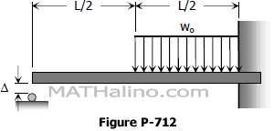
Problem 712 | Propped beam with initial clearance at the roller support
Problem 712
There is a small initial clearance D between the left end of the beam shown in Fig. P-712 and the roller support. Determine the reaction at the roller support after the uniformly distributed load is applied.
Problem 711 | Cantilever beam with free end on top of a simple beam
Problem 711
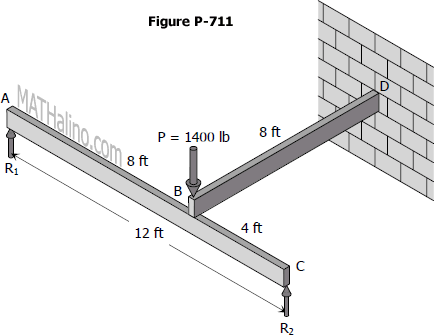
A cantilever beam BD rests on a simple beam AC as shown in Fig. P-711. Both beams are of the same material and are 3 in wide by 8 in deep. If they jointly carry a load P = 1400 lb, compute the maximum flexural stress developed in the beams.
Problem 710 | Two simple beams at 90 degree to each other
Problem 710
Two timber beams are mounted at right angles and in contact with each other at their midpoints. The upper beam A is 2 in wide by 4 in deep and simply supported on an 8-ft span; the lower beam B is 3 in wide by 8 in deep and simply supported on a 10-ft span. At their cross-over point, they jointly support a load P = 2000 lb. Determine the contact force between the beams.
Problem 709 | Propped Beam with Spring Support
Example 06
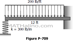
The beam in Figure PB-006 is supported at the left by a spring that deflects 1 inch for each 300 lb. For the beam E = 1.5 × 10⁶ psi and I = 144 in4. Compute the deflection of the spring.
- Read more about Problem 709 | Propped Beam with Spring Support
- Log in or register to post comments
Problem 708 | Two Indentical Cantilever Beams
Problem 708
Two identical cantilever beams in contact at their ends support a distributed load over one of them as shown in Fig. P-708. Determine the restraining moment at each wall.
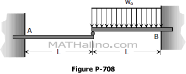
- Read more about Problem 708 | Two Indentical Cantilever Beams
- Log in or register to post comments
Problem 707 | Propped Beam with Moment Load
Problem 707
A couple M is applied at the propped end of the beam shown in Fig. P-707. Compute R at the propped end and also the wall restraining moment.
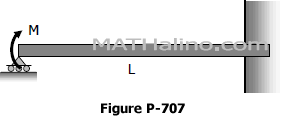
- Read more about Problem 707 | Propped Beam with Moment Load
- Log in or register to post comments
Problem 706 | Solution of Propped Beam with Decreasing Load
Example 03
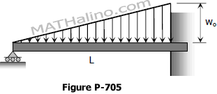
The propped beam shown in Fig. P -706 is loaded by decreasing triangular load varying from wo from the simple end to zero at the fixed end. Find the support reactions and sketch the shear and moment diagrams
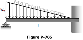
The Three-Moment Equation
The three-moment equation gives us the relation between the moments between any three points in a beam and their relative vertical distances or deviations. This method is widely used in finding the reactions in a continuous beam.
Consider three points on the beam loaded as shown.
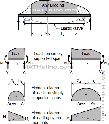
- Read more about The Three-Moment Equation
- Log in or register to post comments
Continuous Beams
Continuous beams are those that rest over three or more supports, thereby having one or more redundant support reactions.
These section includes
1. Generalized form of three-moment equation
2. Factors for three-moment equation
3. Application of the three-moment equation
4. Reactions of continuous beams
5. Shear and moment diagrams of continuous beams
6. Continuous beams with fixed ends
7. Deflection determined by three-moment equation
8. Moment distribution method
- Read more about Continuous Beams
- Log in or register to post comments

