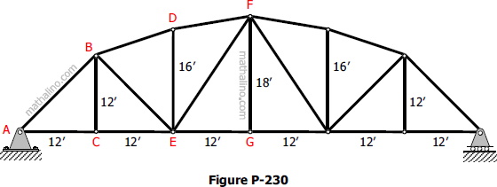
Problem 356 | Equilibrium of Non-Concurrent Force System
Problem 356
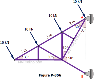
The cantilever truss shown in Fig. P-356 is supported by a hinge at A and a strut BC. Determine the reactions at A and B.
Problem 356
The cantilever truss shown in Fig. P-356 is supported by a hinge at A and a strut BC. Determine the reactions at A and B.

Problem 355
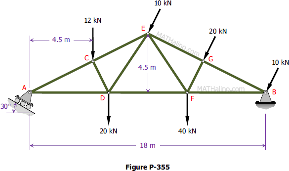
Determine the reactions at A and B on the Fink truss shown in Fig. P-355. Members CD and FG are respectively perpendicular to AE and BE at their midpoints.
Problem 354
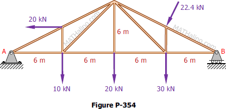
Compute the total reactions at A and B on the truss shown in Fig. P-354.
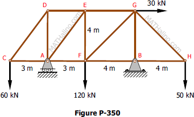
Problem 350
Compute the total reactions at A and B for the truss shown in Fig. P-350.
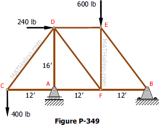
Problem 349
The truss shown in Fig. P-349 is supported on roller at A and hinge at B. Solve for the components of the reactions.
Problem 323
The truss shown in Fig. P-323 is supported by a hinge at A and a roller at B. A load of 20 kN is applied at C. Determine the reactions at A and B.

Problem 322
The Fink truss shown in Fig. P-322 is supported by a roller at A and a hinge at B. The given loads are normal to the inclined member. Determine the reactions at A and B. Hint: Replace the loads by their resultant.

Problem 250
The cantilever truss shown in Fig. P-250 carries a vertical load of 10.8 kN. The truss is supported by bearing at A and B which exert the forces Av, Ah, and Bh. The four forces shown constitute two couples which must have opposite moment effects to prevent movement of the truss. Determine the magnitude of the supporting forces.

Problem 241
Locate the amount and position of the resultant of the loads acting on the Fink truss in Fig. P-241.

Problem 230
For the truss shown in Fig. P-230, compute the perpendicular distance from E and from G to the line BD. Hint: Imagine a force F directed along BD and compute its moment in terms of its components about E and about G. Then equate these results to the definition of moment M = Fd to compute the required perpendicular distances.
