Truss member

Problem 004-mj | Method of Joints

Problem 004-mj
The truss pinned to the floor at D, and supported by a roller at point A is loaded as shown in Fig. T-06. Determine the force in member CG.
 

Truss with rectangular arrangement of members at the center


Problem 003-mj | Method of Joints

Problem 003-mj
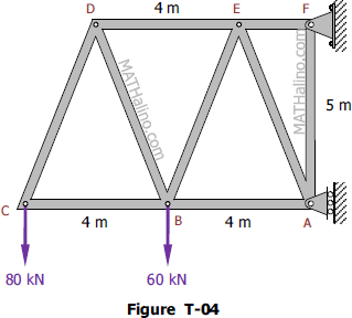
Find the force in each member of the truss shown in Fig. T-04.
 

005-cantilever-truss.gif


Problem 003-ms | Method of Sections

Problem 003-ms
The truss in Fig. T-04 is pinned to the wall at point F, and supported by a roller at point C. Calculate the force (tension or compression) in members BC, BE, and DE.
 

Cantilever truss by method of sections
Figure T-04


Problem 002-ms | Method of Sections

Problem 002-ms
The roof truss shown in Fig. T-03 is pinned at point A, and supported by a roller at point H. Determine the force in member DG.
 

Roof truss by method of sections


Problem 001-ms | Method of Sections

Problem 001-ms
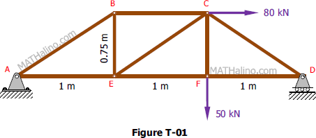
From the truss in Fig. T-01, determine the force in mebers BC, CE, and EF.
 

001-3m-truss-given.gif


Problem 403 | Method of Joints

Problem 403
Determine the force in each bar of the truss shown in Fig. P-403.
 

Tower-like truss


Problem 001-mj | Method of Joints

Problem
Find the force acting in all members of the truss shown in Figure T-01.
 

001-3m-truss-given.gif


230 Distance from truss member to truss joint

Problem 230
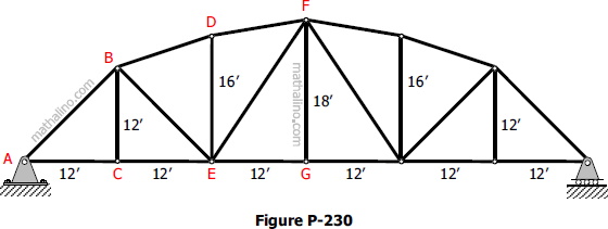
For the truss shown in Fig. P-230, compute the perpendicular distance from E and from G to the line BD. Hint: Imagine a force F directed along BD and compute its moment in terms of its components about E and about G. Then equate these results to the definition of moment M = Fd to compute the required perpendicular distances.
 

Symmetrical Truss


Pages

Subscribe to RSS - Truss member