Shearing Stress
Solution to Problem 335 | Flanged bolt couplings
Problem 335
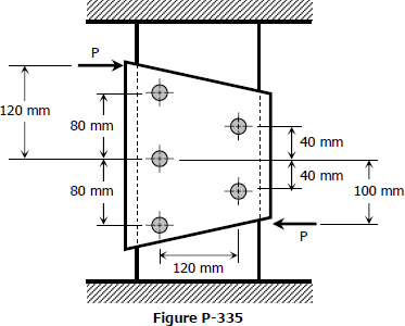
The plate shown in Fig. P-335 is fastened to the fixed member by five 10-mm-diameter rivets. Compute the value of the loads P so that the average shearing stress in any rivet does not exceed 70 MPa. (Hint: Use the results of Prob. 332.)
- Read more about Solution to Problem 335 | Flanged bolt couplings
- Log in or register to post comments
Solution to Problem 334 | Flanged bolt couplings
Problem 334
Six 7/8-in-diameter rivets fasten the plate in Fig. P-334 to the fixed member. Using the results of Prob. 332, determine the average shearing stress caused in each rivet by the 14 kip loads. What additional loads P can be applied before the shearing stress in any rivet exceeds 8000 psi?
- Read more about Solution to Problem 334 | Flanged bolt couplings
- Log in or register to post comments
Solution to Problem 333 | Flanged bolt couplings
Problem 333
A plate is fastened to a fixed member by four 20-mm-diameter rivets arranged as shown in Fig. P-333. Compute the maximum and minimum shearing stress developed.
- Read more about Solution to Problem 333 | Flanged bolt couplings
- Log in or register to post comments
Solution to Problem 332 | Flanged bolt couplings
Problem 332
In a rivet group subjected to a twisting couple T, show that the torsion formula τ = Tρ/J can be used to find the shearing stress τ at the center of any rivet. Let J = ΣAρ2, where A is the area of a rivet at the radial distance ρ from the centroid of the rivet group.
- Read more about Solution to Problem 332 | Flanged bolt couplings
- Log in or register to post comments
Solution to Problem 331 | Flanged bolt couplings
Problem 331
A flanged bolt coupling consists of six ½-in. steel bolts evenly spaced around a bolt circle 12 in. in diameter, and four ¾-in. aluminum bolts on a concentric bolt circle 8 in. in diameter. What torque can be applied without exceeding 9000 psi in the steel or 6000 psi in the aluminum? Assume Gst = 12 × 106 psi and Gal = 4 × 10⁶ psi.
- Read more about Solution to Problem 331 | Flanged bolt couplings
- Log in or register to post comments
Solution to Problem 324 Torsion
Problem 324
The compound shaft shown in Fig. P-324 is attached to rigid supports. For the bronze segment AB, the maximum shearing stress is limited to 8000 psi and for the steel segment BC, it is limited to 12 ksi. Determine the diameters of each segment so that each material will be simultaneously stressed to its permissible limit when a torque T = 12 kip·ft is applied. For bronze, G = 6 × 10⁶ psi and for steel, G = 12 × 106 psi.
- Read more about Solution to Problem 324 Torsion
- Log in or register to post comments
Solution to Problem 323 Torsion
Problem 323
A shaft composed of segments AC, CD, and DB is fastened to rigid supports and loaded as shown in Fig. P-323. For bronze, G = 35 GPa; aluminum, G = 28 GPa, and for steel, G = 83 GPa. Determine the maximum shearing stress developed in each segment.
- Read more about Solution to Problem 323 Torsion
- Log in or register to post comments
Solution to Problem 322 Torsion
Problem 322
A solid steel shaft is loaded as shown in Fig. P-322. Using G = 83 GPa, determine the required diameter of the shaft if the shearing stress is limited to 60 MPa and the angle of rotation at the free end is not to exceed 4 deg.
- Read more about Solution to Problem 322 Torsion
- Log in or register to post comments
Solution to Problem 320 Torsion
Problem 320
In Prob. 319, determine the ratio of lengths b/a so that each material will be stressed to its permissible limit. What torque T is required?
- Read more about Solution to Problem 320 Torsion
- 2 comments
- Log in or register to post comments


