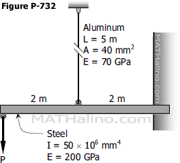
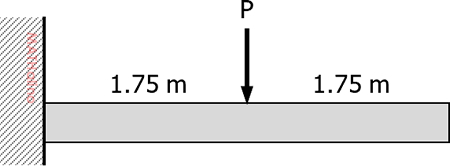
cantilever beam

Situation
A cantilever beam, 3.5 m long, carries a concentrated load, P, at mid-length.

Given:
P = 200 kN
Beam Modulus of Elasticity, E = 200 GPa
Beam Moment of Inertia, I = 60.8 × 106 mm4


2018-nov-design-cantilever-beam-given.jpg


1.   How much is the deflection (mm) at mid-length?

A.   1.84 C.   23.50
B.   29.40 D.   14.70

2.   What force (kN) should be applied at the free end to prevent deflection?

A.   7.8 C.   62.5
B.   41.7 D.   100.0

3.   To limit the deflection at mid-length to 9.5 mm, how much force (kN) should be applied at the free end?

A.   54.1 C.   129.3
B.   76.8 D.   64.7


Problem 733 | Cantilever beam with moment load at the free end and supported by a rod at midspan

Problem 733
The load P in Prob. 732 is replaced by a counterclockwise couple M. Determine the maximum value of M if the stress in the vertical rod is not to exceed 150 MPa.
 

Problem 732 | Cantilever beam supported by a cable at midspan

Problem 732
The midpoint of the steel in Fig. P-732 is connected to the vertical aluminum rod. Determine the maximum value of P if the stress in the rod is not to exceed 120 MPa.
 

Cantilever beam supported with aluminum rod at the midspan


Problem 731 | Cantilever beam supported by cable at the free-end

Problem 731
The beam shown in Fig. P-731 is connected to a vertical rod. If the beam is horizontal at a certain temperature, determine the increase in stress in the rod if the temperature of the rod drops 90°F. Both the beam and the rod are made of steel with E = 29 × 106 psi. For the beam, use I = 154 in.4
 

Cantilever beam hanged with cable at the free end

Problem 711 | Cantilever beam with free end on top of a simple beam

Problem 711
A cantilever beam BD rests on a simple beam AC as shown in Fig. P-711. Both beams are of the same material and are 3 in wide by 8 in deep. If they jointly carry a load P = 1400 lb, compute the maximum flexural stress developed in the beams.
 

The ends of cantilever beam rests on top of simple beam at the third point.


Problem 708 | Two Indentical Cantilever Beams

Problem 708
Two identical cantilever beams in contact at their ends support a distributed load over one of them as shown in Fig. P-708. Determine the restraining moment at each wall.
 

Two cantilever beams.


Method of Superposition | Beam Deflection

The slope or deflection at any point on the beam is equal to the resultant of the slopes or deflections at that point caused by each of the load acting separately.
 

Solution to Problem 648 | Deflection of Cantilever Beams

Problem 648
For the cantilever beam loaded as shown in Fig. P-648, determine the deflection at a distance x from the support.
 

Cantilever beam loaded with uniformly increasing load


Solution to Problem 647 | Deflection of Cantilever Beams

Problem 647
Find the maximum value of EIδ for the beam shown in Fig. P-647.
 

Triangle load over half end of cantilever beam


Solution to Problem 646 | Deflection of Cantilever Beams

Problem 646
For the beam shown in Fig. P-646, determine the value of I that will limit the maximum deflection to 0.50 in. Assume that E = 1.5 × 10⁶ psi.
 

Cantilever beam with triangular load at the middle


Pages

Subscribe to RSS - cantilever beam