Simply Supported Beam with Support Added at Midspan to Prevent Excessive Deflection

Situation
A simply supported beam has a span of 12 m. The beam carries a total uniformly distributed load of 21.5 kN/m.
1.   To prevent excessive deflection, a support is added at midspan. Calculate the resulting moment (kN·m) at the added support.

A.   64.5 C.   258.0
B.   96.8 D.   86.0

2.   Calculate the resulting maximum positive moment (kN·m) when a support is added at midspan.

A.   96.75 C.   108.84
B.   54.42 D.   77.40

3.   Calculate the reaction (kN) at the added support.

A.   48.38 C.   161.2
B.   96.75 D.   80.62


Limit the Deflection of Cantilever Beam by Applying Force at the Free End

Situation
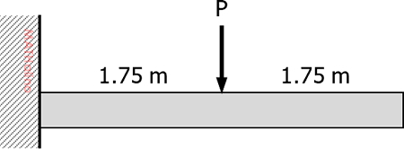
A cantilever beam, 3.5 m long, carries a concentrated load, P, at mid-length.

Given:
P = 200 kN
Beam Modulus of Elasticity, E = 200 GPa
Beam Moment of Inertia, I = 60.8 × 106 mm4


2018-nov-design-cantilever-beam-given.jpg


1.   How much is the deflection (mm) at mid-length?

A.   1.84 C.   23.50
B.   29.40 D.   14.70

2.   What force (kN) should be applied at the free end to prevent deflection?

A.   7.8 C.   62.5
B.   41.7 D.   100.0

3.   To limit the deflection at mid-length to 9.5 mm, how much force (kN) should be applied at the free end?

A.   54.1 C.   129.3
B.   76.8 D.   64.7


Support Added at the Midspan of Simple Beam to Prevent Excessive Deflection

Situation
A simply supported steel beam spans 9 m. It carries a uniformly distributed load of 10 kN/m, beam weight already included.

Given Beam Properties:
Area = 8,530 mm2
Depth = 306 mm
Flange Width = 204 mm
Flange Thickness = 14.6 mm
Moment of Inertia, Ix = 145 × 106 mm4
Modulus of Elasticity, E = 200 GPa

1.   What is the maximum flexural stress (MPa) in the beam?

A.   107 C.   142
B.   54 D.   71

2.   To prevent excessive deflection, the beam is propped at midspan using a pipe column. Find the resulting axial stress (MPa) in the column

Given Column Properties:
Outside Diameter = 200 mm
Thickness = 10 mm
Height, H = 4 m
Modulus of Elasticity, E = 200 GPa
A.   4.7 C.   18.8
B.   9.4 D.   2.8

3.   How much is the maximum bending stress (MPa) in the propped beam?

A.   26.7 C.   15.0
B.   17.8 D.   35.6


Continuous Beam With Equal Support Reactions

Situation
A beam 100 mm × 150 mm carrying a uniformly distributed load of 300 N/m rests on three supports spaced 3 m apart as shown below. The length x is so calculated in order that the reactions at all supports shall be the same.
 

design-practice-2-given.png


1.   Find x in meters.

A.   1.319 C.   1.217
B.   1.139 D.   1.127

2.   Find the moment at B in N·m.

A.   -240 C.   -242
B.   -207 D.   -226

3.   Calculate the reactions in Newton.

A.   843.4 C.   863.8
B.   425.4 D.   827.8


Continuous Beam With a Gap and a Zero Moment in Interior Support

Situation
A beam of uniform cross section whose flexural rigidity EI = 2.8 × 10¹¹ N·mm2, is placed on three supports as shown. Support B is at small gap Δ so that the moment at B is zero.
 

design-practice-1-given.gif


1.   Calculate the reaction at A.

A.   4.375 kN C.   5.437 kN
B.   8.750 kN D.   6.626 kN

2.   What is the reaction at B?

A.   4.375 kN C.   5.437 kN
B.   8.750 kN D.   6.626 kN

3.   Find the value of Δ.

A.   46 mm C.   34 mm
B.   64 mm D.   56 mm


Maximum Stress of Truss Member Due to Moving Loads

Situation
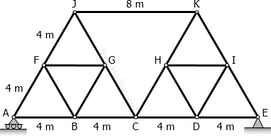
The bridge truss shown in the figure is to be subjected by uniform load of 10 kN/m and a point load of 30 kN, both are moving across the bottom chord
 

2014-may-design-truss-equilateral-triangle-given.gif


Calculate the following:
1.   The maximum axial load on member JK.

A.   64.59 kN C.   -64.59 kN
B.   -63.51 kN D.   63.51 kN

2.   The maximum axial load on member BC.

A.   47.63 kN C.   -47.63 kN
B.   -74.88 kN D.   74.88 kN

3.   The maximum compression force and maximum tension force on member CG.

A.   -48.11 kN and 16.36 kN
B.   Compression = 0; Tension = 16.36 kN
C.   -16.36 kN and 48.11 kN
D.   Compression = 48.11 kN; Tension = 0