Solution to Problem 254 Statically Indeterminate
Problem 254
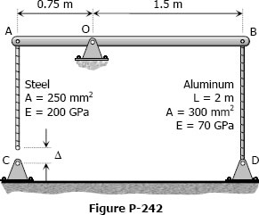
As shown in Fig. P-254, a rigid bar with negligible mass is pinned at O and attached to two vertical rods. Assuming that the rods were initially stress-free, what maximum load P can be applied without exceeding stresses of 150 MPa in the steel rod and 70 MPa in the bronze rod.

- Read more about Solution to Problem 254 Statically Indeterminate
- Log in or register to post comments