couple

Solution to Problem 624 | Moment Diagram by Parts

Problem 624
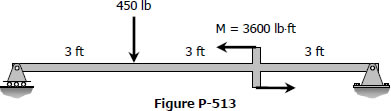
For the beam loaded as shown in Fig. P-624, compute the moment of area of the M diagrams between the reactions about both the left and the right reaction.
 

Simple beam with moment and point loads


Moment Diagram by Parts

The moment-area method of finding the deflection of a beam will demand the accurate computation of the area of a moment diagram, as well as the moment of such area about any axis. To pave its way, this section will deal on how to draw moment diagram by parts and to calculate the moment of such diagrams about a specified axis.
 

Solution to Problem 619 | Double Integration Method

Problem 619
Determine the value of EIy midway between the supports for the beam loaded as shown in Fig. P-619.
 

Overhang beam with moment and uniform loads


Solution to Problem 618 | Double Integration Method

Problem 618
A simply supported beam carries a couple M applied as shown in Fig. P-618. Determine the equation of the elastic curve and the deflection at the point of application of the couple. Then letting a = L and a = 0, compare your solution of the elastic curve with cases 11 and 12 in the Summary of Beam Loadings.
 

Simply supported beam carrying a couple


Solution to Problem 617 | Double Integration Method

Problem 617
Replace the load P in Prob. 616 by a clockwise couple M applied at the right end and determine the slope and deflection at the right end.
 

Solution to Problem 582 | Design for Flexure and Shear

Problem 582
Find the cross-sectional dimensions of the smallest square beam that can be loaded as shown in Fig. P-582 if fv ≤ 1.0 MPa and fb ≤ 8 MPa.
 

Solution to Problem 513 | Flexure Formula

Problem 513
A rectangular steel beam, 2 in wide by 3 in deep, is loaded as shown in Fig. P-513. Determine the magnitude and the location of the maximum flexural stress.
 

Rectangular steel simple beam beam


Solution to Problem 506 | Flexure Formula

Problem 506
A flat steel bar, 1 inch wide by ¼ inch thick and 40 inches long, is bent by couples applied at the ends so that the midpoint deflection is 1.0 inch. Compute the stress in the bar and the magnitude of the couples. Use E = 29 × 106 psi.
 

Solution to Problem 332 | Flanged bolt couplings

Problem 332
In a rivet group subjected to a twisting couple T, show that the torsion formula τ = Tρ/J can be used to find the shearing stress τ at the center of any rivet. Let J = ΣAρ2, where A is the area of a rivet at the radial distance ρ from the centroid of the rivet group.
 

Pages

Subscribe to RSS - couple