bolt

249 - Reactions at the bolts of speed reducer gear box

Problem 249
Fig. P-249 represents the top view of a speed reducer which is geared for a four to one reduction in speed. The torque input at the horizontal shaft C is 100 lb·ft. The torque output at the horizontal shaft D, because of the speed reduction, is 400 lb·ft. Compute the torque reaction at the mounting bolts A and B holding the reducer to the floor. Hint: The torque reaction is caused by the unbalanced torque, which is a couple.
 

Top view of speed reduction gear box


Solution to Problem 599 | Spacing of Rivets or Bolts in Built-Up Beams

Problem 599
A beam is formed by bolting together two W200 × 100 sections as shown in Fig. P-599. It is used to support a uniformly distributed load of 30 kN/m (including the weight of the beam) on a simply supported span of 10 m. Compute the maximum flexural stress and the pitch between bolts that have a shearing strength of 30 kN.
 

Wide Flange on top of the other and bolted together


Solution to Problem 598 | Spacing of Rivets or Bolts in Built-Up Beams

Problem 598
As shown in Fig. P-598, two C380 × 60 channels are riveted together by pairs of 19-mm rivets spaced 200 mm apart along the length of the beam. What maximum vertical shear V can be applied to the section without exceeding the stresses given in Illustrative Problem 591?
 

Bolted Back-to-back Channels


Solution to Problem 597 | Spacing of Rivets or Bolts in Built-Up Beams

Problem 597
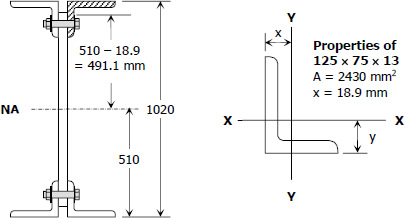
A plate and angle girder similar to that shown in Fig. 5-32 is fabricated by riveting the short legs of four 125 × 75 × 13 mm angles to a web plate 1000 mm by 10 mm to form a section 1020 mm deep. Cover plates, each 300 mm × 10 mm, are then riveted to the flange angles making the overall height 1040 mm. The moment of inertia of the entire section about the NA is I = 4770 × 106 mm4. Using the allowable stresses specified in Illustrative Problem 591, determine the rivet pitch for 22-mm rivets, attaching the angles to the web plate at a section where V = 450 kN.
 

Built-up Girder from Plate and Angles


Solution to Problem 596 | Spacing of Rivets or Bolts in Built-Up Beams

Problem 596
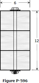
Three planks 4 in by 6 in., arranged as shown in Fig. P-596 and secured by bolts spaced 1 ft apart, are used to support a concentrated load P at the center of a simply supported span 12 ft long. If P causes a maximum flexural stress of 1200 psi, determine the bolt diameters, assuming that the shear between the planks is transmitted by friction only. The bolts are tightened to a tension of 20 ksi and the coefficient of friction between the planks is 0.40.
 

Three Planks Secured by Bolts


Solution to Problem 592 | Spacing of Rivets or Bolts in Built-Up Beams

Problem 592
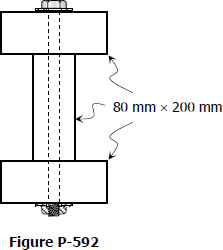
A wide flange section is formed by bolting together three planks, each 80 mm by 200 mm, arranged as shown in Fig. P-592. If each bolt can withstand a shearing force of 8 kN, determine the pitch if the beam is loaded so as to cause a maximum shearing stress of 1.4 MPa.
 

Wide Flanged From Bolting Three Planks


Spacing of Rivets or Bolts in Built-Up Beams

When two or more thin layers of beams are fastened together with a bolt or a rivet so that they act as a unit to gain more strength, it is necessary to design the to size or spacing of these bolts or rivets so that it can carry the shearing force acting between each adjacent layers.
 

Solution to Problem 331 | Flanged bolt couplings

Problem 331
A flanged bolt coupling consists of six ½-in. steel bolts evenly spaced around a bolt circle 12 in. in diameter, and four ¾-in. aluminum bolts on a concentric bolt circle 8 in. in diameter. What torque can be applied without exceeding 9000 psi in the steel or 6000 psi in the aluminum? Assume Gst = 12 × 106 psi and Gal = 4 × 10⁶ psi.
 

Solution to Problem 330 | Flanged bolt couplings

Problem 330
Determine the number of 10-mm-diameter steel bolts that must be used on the 400-mm bolt circle of the coupling described in Prob. 328 to increase the torque capacity to 14 kN·m
 

Solution to Problem 329 | Flanged bolt couplings

Problem 329
A torque of 700 lb-ft is to be carried by a flanged bolt coupling that consists of eight ½-in.-diameter steel bolts on a circle of diameter 12 in. and six ½-in.-diameter steel bolts on a circle of diameter 9 in. Determine the shearing stress in the bolts.
 

Pages

Subscribe to RSS - bolt