Solution to Problem 328 | Flanged bolt couplings
Problem 328
A flanged bolt coupling consists of eight 10-mm-diameter steel bolts on a bolt circle 400 mm in diameter, and six 10-mm-diameter steel bolts on a concentric bolt circle 300 mm in diameter, as shown in Fig. 3-7. What torque can be applied without exceeding a shearing stress of 60 MPa in the bolts?
- Read more about Solution to Problem 328 | Flanged bolt couplings
- Log in or register to post comments
Solution to Problem 327 | Flanged bolt couplings
Problem 327
A flanged bolt coupling consists of ten steel ½-in.-diameter bolts spaced evenly around a bolt circle 14 in. in diameter. Determine the torque capacity of the coupling if the allowable shearing stress in the bolts is 6000 psi.
- Read more about Solution to Problem 327 | Flanged bolt couplings
- Log in or register to post comments
Solution to Problem 326 | Flanged bolt couplings
Problem 326
A flanged bolt coupling consists of ten 20-mm-diameter bolts spaced evenly around a bolt circle 400 mm in diameter. Determine the torque capacity of the coupling if the allowable shearing stress in the bolts is 40 MPa.
- Read more about Solution to Problem 326 | Flanged bolt couplings
- Log in or register to post comments
Solution to Problem 325 Torsion
Problem 325
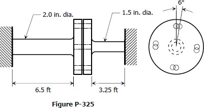
The two steel shaft shown in Fig. P-325, each with one end built into a rigid support have flanges rigidly attached to their free ends. The shafts are to be bolted together at their flanges. However, initially there is a 6° mismatch in the location of the bolt holes as shown in the figure. Determine the maximum shearing stress in each shaft after the shafts are bolted together. Use G = 12 × 106 psi and neglect deformations of the bolts and flanges.
- Read more about Solution to Problem 325 Torsion
- Log in or register to post comments
Solution to Problem 142 Pressure Vessel
Problem 142
A pipe carrying steam at 3.5 MPa has an outside diameter of 450 mm and a wall thickness of 10 mm. A gasket is inserted between the flange at one end of the pipe and a flat plate used to cap the end. How many 40-mm-diameter bolts must be used to hold the cap on if the allowable stress in the bolts is 80 MPa, of which 55 MPa is the initial stress? What circumferential stress is developed in the pipe? Why is it necessary to tighten the bolt initially, and what will happen if the steam pressure should cause the stress in the bolts to be twice the value of the initial stress?
- Read more about Solution to Problem 142 Pressure Vessel
- Log in or register to post comments
Solution to Problem 129 Bearing Stress
Problem 129
- Read more about Solution to Problem 129 Bearing Stress
- Log in or register to post comments
Solution to Problem 127 Bearing Stress
Problem 127
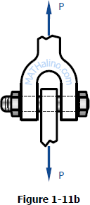
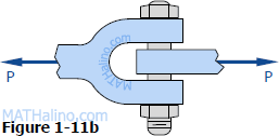
In the clevis shown in Fig. 1-11b, find the minimum bolt diameter and the minimum thickness of each yoke that will support a load P = 14 kips without exceeding a shearing stress of 12 ksi and a bearing stress of 20 ksi.

- Read more about Solution to Problem 127 Bearing Stress
- Log in or register to post comments
Solution to Problem 117 Shear Stress
Problem 117
Find the smallest diameter bolt that can be used in the clevis shown in Fig. 1-11b if P = 400 kN. The shearing strength of the bolt is 300 MPa.

- Read more about Solution to Problem 117 Shear Stress
- Log in or register to post comments

