Solution to Problem 325 Torsion

Problem 325
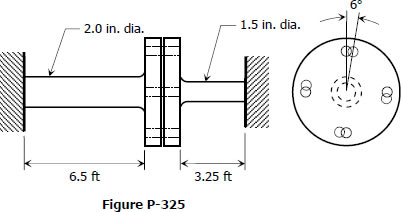
The two steel shaft shown in Fig. P-325, each with one end built into a rigid support have flanges rigidly attached to their free ends. The shafts are to be bolted together at their flanges. However, initially there is a 6° mismatch in the location of the bolt holes as shown in the figure. Determine the maximum shearing stress in each shaft after the shafts are bolted together. Use G = 12 × 106 psi and neglect deformations of the bolts and flanges.
 

Shafts connected through flanges


316 Permissible Torque That Can Be Applied to a Compound Shaft

Problem 316
A compound shaft consisting of a steel segment and an aluminum segment is acted upon by two torques as shown in Fig. P-316. Determine the maximum permissible value of T subject to the following conditions: τst ≤ 83 MPa, τal ≤ 55 MPa, and the angle of rotation of the free end is limited to 6°. For steel, G = 83 GPa and for aluminum, G = 28 GPa.
 

Figure P-316

315 Power Applied and Removed at Shaft Gears

Problem 315
A 5-m steel shaft rotating at 2 Hz has 70 kW applied at a gear that is 2 m from the left end where 20 kW are removed. At the right end, 30 kW are removed and another 20 kW leaves the shaft at 1.5 m from the right end. (a) Find the uniform shaft diameter so that the shearing stress will not exceed 60 MPa. (b) If a uniform shaft diameter of 100 mm is specified, determine the angle by which one end of the shaft lags behind the other end. Use G = 83 GPa.
 

312 Deformation of Flexible Shaft Made From Steel Wire Encased in Stationary Tube

Problem 312
A flexible shaft consists of a 0.20-in-diameter steel wire encased in a stationary tube that fits closely enough to impose a frictional torque of 0.50 lb·in/in. Determine the maximum length of the shaft if the shearing stress is not to exceed 20 ksi. What will be the angular deformation of one end relative to the other end? G = 12 × 106 psi.