Solution to Problem 275 Thermal Stress
Problem 275
A rigid horizontal bar of negligible mass is connected to two rods as shown in Fig. P-275. If the system is initially stress-free. Calculate the temperature change that will cause a tensile stress of 90 MPa in the brass rod. Assume that both rods are subjected to the change in temperature.
- Read more about Solution to Problem 275 Thermal Stress
- Log in or register to post comments
Solution to Problem 274 Thermal Stress
Problem 274
At what temperature will the aluminum and steel segments in Prob. 273 have numerically equal stress?
- Read more about Solution to Problem 274 Thermal Stress
- Log in or register to post comments
Solution to Problem 273 Thermal Stress
Problem 273
The composite bar shown in Fig. P-273 is firmly attached to unyielding supports. An axial force P = 50 kips is applied at 60°F. Compute the stress in each material at 120°F. Assume α = 6.5 × 10⁻⁶ in/(in·°F) for steel and 12.8 × 10⁻⁶ in/(in·°F) for aluminum.

- Read more about Solution to Problem 273 Thermal Stress
- Log in or register to post comments
Solution to Problem 269 Thermal Stress
Problem 269
As shown in Fig. P-269, there is a gap between the aluminum bar and the rigid slab that is supported by two copper bars. At 10°C, Δ = 0.18 mm. Neglecting the mass of the slab, calculate the stress in each rod when the temperature in the assembly is increased to 95°C. For each copper bar, A = 500 mm2, E = 120 GPa, and α = 16.8 µm/(m·°C). For the aluminum bar, A = 400 mm2, E = 70 GPa, and α = 23.1 µm/(m·°C).

- Read more about Solution to Problem 269 Thermal Stress
- Log in or register to post comments
Solution to Problem 268 Thermal Stress
Problem 268
The rigid bar ABC in Fig. P-268 is pinned at B and attached to the two vertical rods. Initially, the bar is horizontal and the vertical rods are stress-free. Determine the stress in the aluminum rod if the temperature of the steel rod is decreased by 40°C. Neglect the weight of bar ABC.

- Read more about Solution to Problem 268 Thermal Stress
- Log in or register to post comments
Solution to Problem 257 Statically Indeterminate
Problem 257
Three bars AB, AC, and AD are pinned together as shown in Fig. P-257. Initially, the assembly is stress free. Horizontal movement of the joint at A is prevented by a short horizontal strut AE. Calculate the stress in each bar and the force in the strut AE when the assembly is used to support the load W = 10 kips. For each steel bar, A = 0.3 in.2 and E = 29 × 106 psi. For the aluminum bar, A = 0.6 in.2 and E = 10 × 106 psi.

Solution to Problem 249 Statically Indeterminate
Problem 249
There is a radial clearance of 0.05 mm when a steel tube is placed over an aluminum tube. The inside diameter of the aluminum tube is 120 mm, and the wall thickness of each tube is 2.5 mm. Compute the contact pressure and tangential stress in each tube when the aluminum tube is subjected to an internal pressure of 5.0 MPa.
Solution to Problem 242 Statically Indeterminate
Problem 242
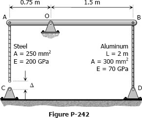
The assembly in Fig. P-242 consists of a light rigid bar AB, pinned at O, that is attached to the steel and aluminum rods. In the position shown, bar AB is horizontal and there is a gap, Δ = 5 mm, between the lower end of the steel rod and its pin support at C. Compute the stress in the aluminum rod when the lower end of the steel rod is attached to its support.
- Read more about Solution to Problem 242 Statically Indeterminate
- Log in or register to post comments
Solution to Problem 239 Statically Indeterminate
Problem 239
The rigid platform in Fig. P-239 has negligible mass and rests on two steel bars, each 250.00 mm long. The center bar is aluminum and 249.90 mm long. Compute the stress in the aluminum bar after the center load P = 400 kN has been applied. For each steel bar, the area is 1200 mm2 and E = 200 GPa. For the aluminum bar, the area is 2400 mm2 and E = 70 GPa.

- Read more about Solution to Problem 239 Statically Indeterminate
- Log in or register to post comments
Solution to Problem 211 Axial Deformation
Problem 211
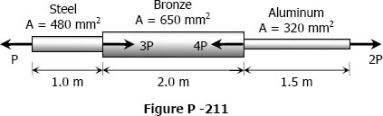
A bronze bar is fastened between a steel bar and an aluminum bar as shown in Fig. p-211. Axial loads are applied at the positions indicated. Find the largest value of P that will not exceed an overall deformation of 3.0 mm, or the following stresses: 140 MPa in the steel, 120 MPa in the bronze, and 80 MPa in the aluminum. Assume that the assembly is suitably braced to prevent buckling. Use Est = 200 GPa, Eal = 70 GPa, and Ebr = 83 GPa.
- Read more about Solution to Problem 211 Axial Deformation
- Log in or register to post comments