February 2009
Floor Framing
In floor framing, the subfloor is supported by light beams called floor joists or simply joists which in turn supported by heavier beams called girders then girders pass the load to columns. Typically, joist act as simply supported beam carrying a uniform load of magnitude p over an area of sL, where
- Read more about Floor Framing
- Log in or register to post comments
Economic Sections
From the flexure formula $f_b = My / I$, it can be seen that the bending stress at the neutral axis, where $y = 0$, is zero and increases linearly outwards. This means that for a rectangular or circular section a large portion of the cross section near the middle section is understressed.
For steel beams or composite beams, instead of adopting the rectangular shape, the area may be arranged so as to give more area on the outer fiber and maintaining the same overall depth, and saving a lot of weight.
- Read more about Economic Sections
- Log in or register to post comments
Section Modulus
In the formula
- Read more about Section Modulus
- Log in or register to post comments
Flexure Formula
- Read more about Flexure Formula
- Log in or register to post comments
Stresses in Beams
Stresses in Beams
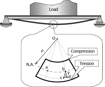
Forces and couples acting on the beam cause bending (flexural stresses) and shearing stresses on any cross section of the beam and deflection perpendicular to the longitudinal axis of the beam. If couples are applied to the ends of the beam and no forces act on it, the bending is said to be pure bending. If forces produce the bending, the bending is called ordinary bending.
- Read more about Stresses in Beams
- Log in or register to post comments
Moving Loads
Moving Loads
From the previous section, we see that the maximum moment occurs at a point of zero shears. For beams loaded with concentrated loads, the point of zero shears usually occurs under a concentrated load and so the maximum moment.
Beams and girders such as in a bridge or an overhead crane are subject to moving concentrated loads, which are at fixed distance with each other. The problem here is to determine the moment under each load when each load is in a position to cause a maximum moment. The largest value of these moments governs the design of the beam.
- Read more about Moving Loads
- Log in or register to post comments

