January 2009
Solution to Problem 337 | Torsion of thin-walled tube
Problem 337
A torque of 600 N·m is applied to the rectangular section shown in Fig. P-337. Determine the wall thickness t so as not to exceed a shear stress of 80 MPa. What is the shear stress in the short sides? Neglect stress concentration at the corners.
- Read more about Solution to Problem 337 | Torsion of thin-walled tube
- Log in or register to post comments
Torsion of thin-walled tube
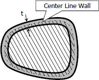
The torque applied to thin-walled tubes is expressed as

- Read more about Torsion of thin-walled tube
- Log in or register to post comments
Solution to Problem 335 | Flanged bolt couplings
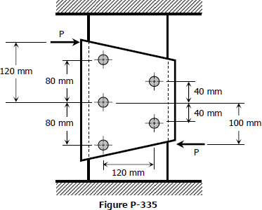
Problem 335
The plate shown in Fig. P-335 is fastened to the fixed member by five 10-mm-diameter rivets. Compute the value of the loads P so that the average shearing stress in any rivet does not exceed 70 MPa. (Hint: Use the results of Prob. 332.)
- Read more about Solution to Problem 335 | Flanged bolt couplings
- Log in or register to post comments
Solution to Problem 334 | Flanged bolt couplings
Problem 334
Six 7/8-in-diameter rivets fasten the plate in Fig. P-334 to the fixed member. Using the results of Prob. 332, determine the average shearing stress caused in each rivet by the 14 kip loads. What additional loads P can be applied before the shearing stress in any rivet exceeds 8000 psi?
- Read more about Solution to Problem 334 | Flanged bolt couplings
- Log in or register to post comments
Solution to Problem 333 | Flanged bolt couplings
Problem 333
A plate is fastened to a fixed member by four 20-mm-diameter rivets arranged as shown in Fig. P-333. Compute the maximum and minimum shearing stress developed.
- Read more about Solution to Problem 333 | Flanged bolt couplings
- Log in or register to post comments
Solution to Problem 332 | Flanged bolt couplings
Problem 332
In a rivet group subjected to a twisting couple T, show that the torsion formula τ = Tρ/J can be used to find the shearing stress τ at the center of any rivet. Let J = ΣAρ2, where A is the area of a rivet at the radial distance ρ from the centroid of the rivet group.
- Read more about Solution to Problem 332 | Flanged bolt couplings
- Log in or register to post comments
Solution to Problem 331 | Flanged bolt couplings
Problem 331
A flanged bolt coupling consists of six ½-in. steel bolts evenly spaced around a bolt circle 12 in. in diameter, and four ¾-in. aluminum bolts on a concentric bolt circle 8 in. in diameter. What torque can be applied without exceeding 9000 psi in the steel or 6000 psi in the aluminum? Assume Gst = 12 × 106 psi and Gal = 4 × 10⁶ psi.
- Read more about Solution to Problem 331 | Flanged bolt couplings
- Log in or register to post comments
Solution to Problem 330 | Flanged bolt couplings
Problem 330
Determine the number of 10-mm-diameter steel bolts that must be used on the 400-mm bolt circle of the coupling described in Prob. 328 to increase the torque capacity to 14 kN·m
- Read more about Solution to Problem 330 | Flanged bolt couplings
- Log in or register to post comments


