HomeMATHalinoEngineering Math Review

Search form

Login • Register

  • Home
    • Recent
    • Glossary
    • About
  • Algebra
    • Derivation of Formulas
    • Engineering Economy
    • General Engineering
  • Trigo
    • Spherical Trigonometry
  • Geometry
    • Solid Geometry
    • Analytic Geometry
  • Calculus
    • Integral Calculus
    • Differential Equations
    • Advance Engineering Mathematics
  • Mechanics
    • Strength of Materials
    • Structural Analysis
  • CE
    • CE Board: Math
    • CE Board: Hydro Geo
    • CE Board: Design
    • Surveying
    • Hydraulics
    • Timber Design
    • Reinforced Concrete
    • Geotechnical Engineering
  • Courses
    • Exams
    • Old MCQ
  • Forums
    • Basic Engineering Math
    • Calculus
    • Mechanics
    • General Discussions
  • Blogs

Breadcrumbs

You are here:

  1. Home
  2. Maximum Compressive Stress

Maximum Compressive Stress

Maximum stresses on a pole subjected to combined loadings

Situation
The solid pole shown in the figure is loaded with a vertical load P = 25 kN and lateral load H = 0.95 kN. The pole is 3 m high, 300 mm diameter and weighs 22 kN/m3.
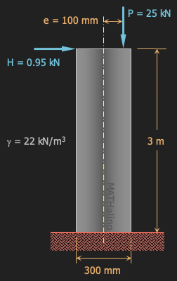
 

2012-may-design-pole-under-combined-loadings.png


  • Read more about Maximum stresses on a pole subjected to combined loadings
  • Log in or register to post comments

Problem 917 | Combined Axial and Bending

Problem 917
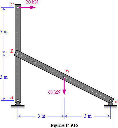
For the structure in Problem 916, calculate the maximum compressive stress in bar ABC if its cross section is 200 mm square.
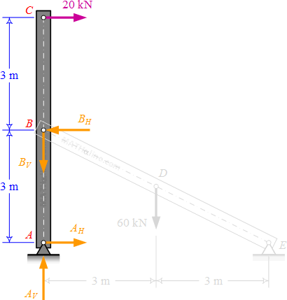
 

916-fbd-member-abc.gif


  • Read more about Problem 917 | Combined Axial and Bending
  • Log in or register to post comments

Problem 916 | Combined Axial and Bending

Problem 916
For the structure shown in Figure P-916 is hinged to fixed supports at A and E. Compute the maximum compressive stress developed in bar BDE if its cross section is 200 mm square. Neglect the weights of the members.
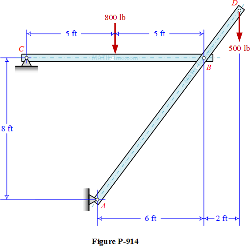
 

916-given-structural-assembly.gif


  • Read more about Problem 916 | Combined Axial and Bending
  • Log in or register to post comments

Problem 914 | Combined Axial and Bending

Problem 914
The structure shown in Figure P-914 is hinged to fixed is hinged to fixed supports at A and C. Assume that the pin connections at A, B, and C are frictionless. The bars are each 4 in. by 4 in. in section. Compute the maximum compressive stress developed in bar AD.
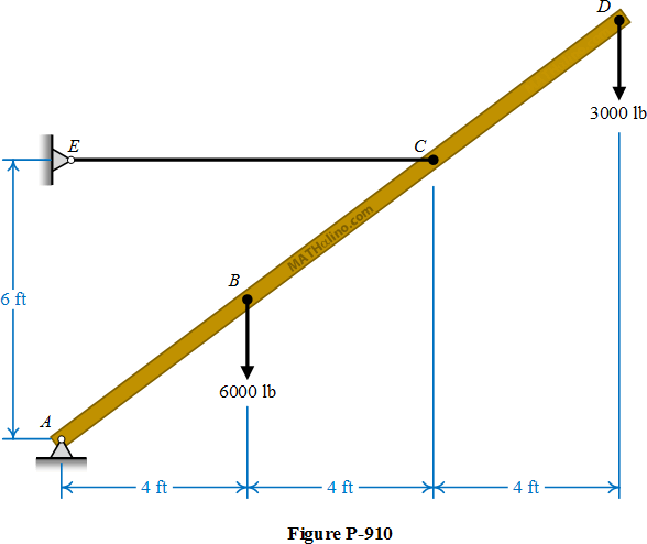
 

914-two-bar-structure.gif


  • Read more about Problem 914 | Combined Axial and Bending
  • Log in or register to post comments

Problem 910 | Combined Axial and Bending

Problem 910
A timber beam AD, 6 in. thick by 10 in. high and loaded as shown in Figure P-910, is pinned at its lower end and supported by a horizontal cable CE. Compute the maximum compressive stress developed in the beam.
 

910-boom.gif


  • Read more about Problem 910 | Combined Axial and Bending
  • Log in or register to post comments
Home • Forums • Blogs • Glossary • Recent
About • Contact us • Terms of Use • Privacy Policy • Hosted by Linode • Powered by Drupal
MATHalino - Engineering Mathematics • Copyright 2025 Jhun Vert • All rights reserved