Situation
The bridge truss shown in the figure is to be subjected by uniform load of 10 kN/m and a point load of 30 kN, both are moving across the bottom chord
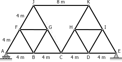
Calculate the following:
1. The maximum axial load on member JK.
| A. 64.59 kN | C. -64.59 kN |
| B. -63.51 kN | D. 63.51 kN |
2. The maximum axial load on member BC.
| A. 47.63 kN | C. -47.63 kN |
| B. -74.88 kN | D. 74.88 kN |
3. The maximum compression force and maximum tension force on member CG.
| A. -48.11 kN and 16.36 kN |
| B. Compression = 0; Tension = 16.36 kN |
| C. -16.36 kN and 48.11 kN |
| D. Compression = 48.11 kN; Tension = 0 |
- Read more about Maximum Stress of Truss Member Due to Moving Loads
- Log in or register to post comments