Problem 323
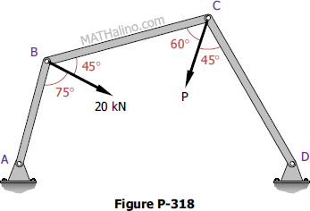
The truss shown in Fig. P-323 is supported by a hinge at A and a roller at B. A load of 20 kN is applied at C. Determine the reactions at A and B.
Problem 322
The Fink truss shown in Fig. P-322 is supported by a roller at A and a hinge at B. The given loads are normal to the inclined member. Determine the reactions at A and B. Hint: Replace the loads by their resultant.
Problem 319
Cords are loop around a small spacer separating two cylinders each weighing 400 lb and pass, as shown in Fig. P-319 over a frictionless pulleys to weights of 200 lb and 400 lb . Determine the angle θ and the normal pressure N between the cylinders and the smooth horizontal surface.
Problem 318
Three bars, hinged at A and D and pinned at B and C as shown in Fig. P-318, form a four-link mechanism. Determine the value of P that will prevent motion.
Problem 315
The 300-lb force and the 400-lb force shown in Fig. P-315 are to be held in equilibrium by a third force F acting at an unknown angle θ with the horizontal. Determine the values of F and θ.
Problem 313
Figure P-313 represents the concurrent force system acting at a joint of a bridge truss. Determine the value of P and E to maintain equilibrium of the forces.