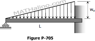
Deflection of Beams

Situation
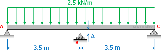
A beam of uniform cross section whose flexural rigidity EI = 2.8 × 10¹¹ N·mm2, is placed on three supports as shown. Support B is at small gap Δ so that the moment at B is zero.
 

design-practice-1-given.gif


1.   Calculate the reaction at A.

A.   4.375 kN C.   5.437 kN
B.   8.750 kN D.   6.626 kN

2.   What is the reaction at B?

A.   4.375 kN C.   5.437 kN
B.   8.750 kN D.   6.626 kN

3.   Find the value of Δ.

A.   46 mm C.   34 mm
B.   64 mm D.   56 mm


Problem 868 | Deflection by Three-Moment Equation

Problem 868
Determine the values of EIδ at midspan and at the ends of the beam loaded as shown in Figure P-868.
 

868-simple-overhanging-beam-triangular-load.gif


Problem 861 | Deflection by Three-Moment Equation

Problem 861
For the beam shown in Fig. P-861, determine the value of EIδ at 2 m and 4 m from the left support.
 

861-simple-beam-given.gif


Problem 732 | Cantilever beam supported by a cable at midspan

Problem 732
The midpoint of the steel in Fig. P-732 is connected to the vertical aluminum rod. Determine the maximum value of P if the stress in the rod is not to exceed 120 MPa.
 

Cantilever beam supported with aluminum rod at the midspan


Problem 731 | Cantilever beam supported by cable at the free-end

Problem 731
The beam shown in Fig. P-731 is connected to a vertical rod. If the beam is horizontal at a certain temperature, determine the increase in stress in the rod if the temperature of the rod drops 90°F. Both the beam and the rod are made of steel with E = 29 × 106 psi. For the beam, use I = 154 in.4
 

Cantilever beam hanged with cable at the free end

Problem 705 | Solution of Propped Beam with Increasing Load

Problem 705
Find the reaction at the simple support of the propped beam shown in Fig. P-705 and sketch the shear and moment diagrams.
 

Propped beam loaded with triangular or uniformly varying load


Problem 704 | Solution of Propped Beam

Reactions of Propped Beam by Double Integration Method | Theory of Structures

Problem 704
Find the reactions at the supports and draw the shear and moment diagrams of the propped beam shown in Fig. P-704.
 

704-propped-beam-uniform-load.gif


Application of Double Integration and Superposition Methods to Restrained Beams

Superposition Method

There are 12 cases listed in the method of superposition for beam deflection.

  • Cantilever beam with...
    1. concentrated load at the free end.
    2. concentrated load anywhere on the beam.
    3. uniform load over the entire span.
    4. triangular load with zero at the free end
    5. moment load at the free end.
  • Simply supported beam with...
    1. concentrated load at the midspan.
    2. concentrated load anywhere on the beam span.
    3. uniform load over the entire span.
    4. triangular load which is zero at one end and full at the other end.
    5. triangular load with zero at both ends and full at the midspan.
    6. moment load at the right support.
    7. moment load at the left support.

See beam deflection by superposition method for details.