Torque

249 - Reactions at the bolts of speed reducer gear box

Problem 249
Fig. P-249 represents the top view of a speed reducer which is geared for a four to one reduction in speed. The torque input at the horizontal shaft C is 100 lb·ft. The torque output at the horizontal shaft D, because of the speed reduction, is 400 lb·ft. Compute the torque reaction at the mounting bolts A and B holding the reducer to the floor. Hint: The torque reaction is caused by the unbalanced torque, which is a couple.
 

Top view of speed reduction gear box


248 - Broken handwheel replaced by lever to close a gate valve

Problem 248
To close a gate valve it is necessary to exert two forces of 60 lb at opposite sides of a handwheel 3 ft in diameter. Through an accident the wheel is broken and the valve must be closed by a thrusting bar through a slot in the valve stem and exerting a force 4 ft out from the center. Determine the force required and draw a free-body diagram of the bar.
 

Solution to Problem 340 | Torsion of thin-walled tube

Problem 340
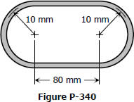
A tube 2 mm thick has the shape shown in Fig. P-340. Find the shearing stress caused by a torque of 600 N·m.
 

Oval thin-walled tube


Solution to Problem 339 | Torsion of thin-walled tube

Problem 339
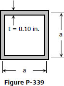
A torque of 450 lb·ft is applied to the square section shown in Fig. P-339. Determine the smallest permissible dimension a if the shearing stress is limited to 6000 psi.
 

Solution to Problem 338 | Torsion of thin-walled tube

Problem 338
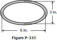
A tube 0.10 in. thick has an elliptical shape shown in Fig. P-338. What torque will cause a shearing stress of 8000 psi?
 

Solution to Problem 337 | Torsion of thin-walled tube

Problem 337
A torque of 600 N·m is applied to the rectangular section shown in Fig. P-337. Determine the wall thickness t so as not to exceed a shear stress of 80 MPa. What is the shear stress in the short sides? Neglect stress concentration at the corners.
 

Solution to Problem 331 | Flanged bolt couplings

Problem 331
A flanged bolt coupling consists of six ½-in. steel bolts evenly spaced around a bolt circle 12 in. in diameter, and four ¾-in. aluminum bolts on a concentric bolt circle 8 in. in diameter. What torque can be applied without exceeding 9000 psi in the steel or 6000 psi in the aluminum? Assume Gst = 12 × 106 psi and Gal = 4 × 10⁶ psi.
 

Solution to Problem 330 | Flanged bolt couplings

Problem 330
Determine the number of 10-mm-diameter steel bolts that must be used on the 400-mm bolt circle of the coupling described in Prob. 328 to increase the torque capacity to 14 kN·m
 

Solution to Problem 329 | Flanged bolt couplings

Problem 329
A torque of 700 lb-ft is to be carried by a flanged bolt coupling that consists of eight ½-in.-diameter steel bolts on a circle of diameter 12 in. and six ½-in.-diameter steel bolts on a circle of diameter 9 in. Determine the shearing stress in the bolts.
 

Solution to Problem 328 | Flanged bolt couplings

Problem 328
A flanged bolt coupling consists of eight 10-mm-diameter steel bolts on a bolt circle 400 mm in diameter, and six 10-mm-diameter steel bolts on a concentric bolt circle 300 mm in diameter, as shown in Fig. 3-7. What torque can be applied without exceeding a shearing stress of 60 MPa in the bolts?
 

Pages

Subscribe to RSS - Torque