Solution to Problem 242 Statically Indeterminate
Problem 242
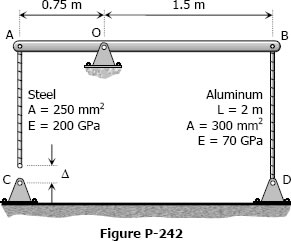
The assembly in Fig. P-242 consists of a light rigid bar AB, pinned at O, that is attached to the steel and aluminum rods. In the position shown, bar AB is horizontal and there is a gap, Δ = 5 mm, between the lower end of the steel rod and its pin support at C. Compute the stress in the aluminum rod when the lower end of the steel rod is attached to its support.
- Read more about Solution to Problem 242 Statically Indeterminate
- Log in or register to post comments