Solution to Problem 599 | Spacing of Rivets or Bolts in Built-Up Beams

Problem 599
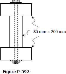
A beam is formed by bolting together two W200 × 100 sections as shown in Fig. P-599. It is used to support a uniformly distributed load of 30 kN/m (including the weight of the beam) on a simply supported span of 10 m. Compute the maximum flexural stress and the pitch between bolts that have a shearing strength of 30 kN.
 

Wide Flange on top of the other and bolted together


Solution to Problem 597 | Spacing of Rivets or Bolts in Built-Up Beams

Problem 597
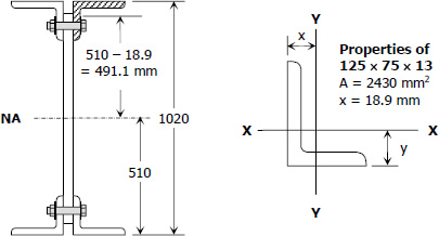
A plate and angle girder similar to that shown in Fig. 5-32 is fabricated by riveting the short legs of four 125 × 75 × 13 mm angles to a web plate 1000 mm by 10 mm to form a section 1020 mm deep. Cover plates, each 300 mm × 10 mm, are then riveted to the flange angles making the overall height 1040 mm. The moment of inertia of the entire section about the NA is I = 4770 × 106 mm4. Using the allowable stresses specified in Illustrative Problem 591, determine the rivet pitch for 22-mm rivets, attaching the angles to the web plate at a section where V = 450 kN.
 

Built-up Girder from Plate and Angles


Solution to Problem 596 | Spacing of Rivets or Bolts in Built-Up Beams

Problem 596
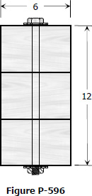
Three planks 4 in by 6 in., arranged as shown in Fig. P-596 and secured by bolts spaced 1 ft apart, are used to support a concentrated load P at the center of a simply supported span 12 ft long. If P causes a maximum flexural stress of 1200 psi, determine the bolt diameters, assuming that the shear between the planks is transmitted by friction only. The bolts are tightened to a tension of 20 ksi and the coefficient of friction between the planks is 0.40.
 

Three Planks Secured by Bolts