frame

Problem 440 - Frame Analysis by Method of Members

Problem 440
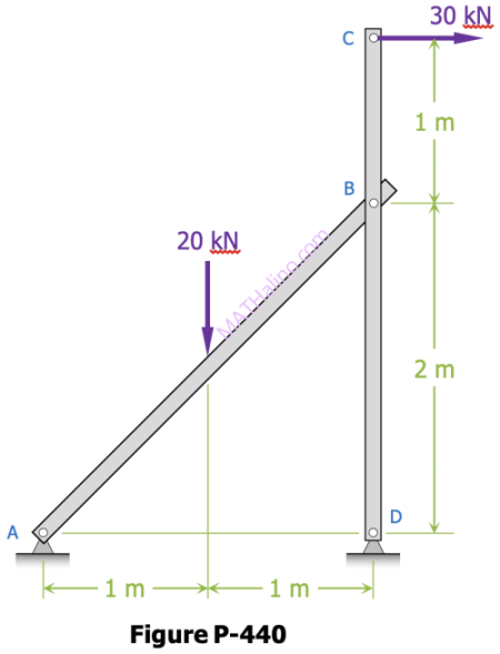
For the frame loaded as shown in Figure P-440, determine the horizontal and vertical components of the pin pressure at B. Specify directions (up or down; left or right) of the force as it acts upon member CD.
 

440-frame-given.gif


Problem 006-fr | Analysis of Simple Frame

Problem 006-fr
In the structure shown in Fig. P-006(FR-H), all members are assumed to be solid rigid members. The system is pinned to the wall at point A and supported by a roller at point E. Calculate the force on member BD and the reactions at A and E.
 

Simple Frame (Inverted L-frame)


Method of Members | Frames Containing Three-Force Members

A three-force member is in general a non-axial member that is not simply in tension or compression. A member of this kind has shear forces perpendicular to the member and subjected to bending loads. If forces are applied to more than two positions on the member, it is three-force member. Any beam is a three-force member according to the above definition.
 

Frames are pin-connected structures with some or all members are three-force members. To analyze a frame, we can disconnect the three-force member from the structure and draw the free-body diagram of the member. This approach is called the method of members.
 

Problem 348 | Equilibrium of Non-Concurrent Force System

Problem 348
The frame shown in Fig. P-348 is supported in pivots at A and B. Each member weighs 5 kN/m. Compute the horizontal reaction at A and the horizontal and vertical components of the reaction at B.
 

Simple Frame Supported in Pivots


257 Horizontal couple equivalent to vertical forces

Problem 257
Replace the system of forces acting on the frame in Fig. P-257 by a resultant R at A and a couple acting horizontally through B and C.
 

257-given-figure.gif


017 Computation of force with given component parallel to a frame member

Problem 017
If the force F shown in Fig. P-017 is resolved into components parallel to the bars AB and BC, the magnitude of the component parallel to bar BC is 4 kN. What are the magnitudes of F and its component parallel to AB?
 

Force F on three-hinge frame


Solution to Problem 440 | Relationship Between Load, Shear, and Moment

Problem 440
A frame ABCD, with rigid corners at B and C, supports the concentrated load as shown in Fig. P-440. (Draw shear and moment diagrams for each of the three parts of the frame.)


Pages

Subscribe to RSS - frame