Solution to Problem 521 | Flexure Formula
Problem 521
A beam made by bolting two C10 × 30 channels back to back, is simply supported at its ends. The beam supports a central concentrated load of 12 kips and a uniformly distributed load of 1200 lb/ft, including the weight of the beam. Compute the maximum length of the beam if the flexural stress is not to exceed 20 ksi.
- Read more about Solution to Problem 521 | Flexure Formula
- Log in or register to post comments
Solution to Problem 513 | Flexure Formula
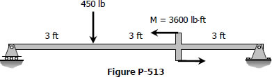
Problem 513
A rectangular steel beam, 2 in wide by 3 in deep, is loaded as shown in Fig. P-513. Determine the magnitude and the location of the maximum flexural stress.
- Read more about Solution to Problem 513 | Flexure Formula
- Log in or register to post comments
Solution to Problem 508 | Flexure Formula
Problem 508
Determine the minimum height h of the beam shown in Fig. P-508 if the flexural stress is not to exceed 20 MPa.
- Read more about Solution to Problem 508 | Flexure Formula
- Log in or register to post comments
Solution to Problem 504 | Flexure Formula
Problem 504
A simply supported beam, 2 in wide by 4 in high and 12 ft long is subjected to a concentrated load of 2000 lb at a point 3 ft from one of the supports. Determine the maximum fiber stress and the stress in a fiber located 0.5 in from the top of the beam at midspan.
- Read more about Solution to Problem 504 | Flexure Formula
- Log in or register to post comments