composite rod

Solution to Problem 266 Thermal Stress

Problem 266
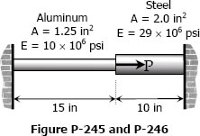
Calculate the increase in stress for each segment of the compound bar shown in Fig. P-266 if the temperature increases by 100°F. Assume that the supports are unyielding and that the bar is suitably braced against buckling.
 

Figure P-266


Solution to Problem 247 Statically Indeterminate

Problem 247
The composite bar in Fig. P-247 is stress-free before the axial loads P1 and P2 are applied. Assuming that the walls are rigid, calculate the stress in each material if P1 = 150 kN and P2 = 90 kN.
 

Solution to Problem 246 Statically Indeterminate

Problem 246
Referring to the composite bar in Problem 245, what maximum axial load P can be applied if the allowable stresses are 10 ksi for aluminum and 18 ksi for steel.
 

Solution to Problem 245 Statically Indeterminate

Problem 245
The composite bar in Fig. P-245 is firmly attached to unyielding supports. Compute the stress in each material caused by the application of the axial load P = 50 kips.
 

Figure 245


Solution to Problem 108 Normal Stress

Problem 108
An aluminum rod is rigidly attached between a steel rod and a bronze rod as shown in Fig. P-108. Axial loads are applied at the positions indicated. Find the maximum value of P that will not exceed a stress in steel of 140 MPa, in aluminum of 90 MPa, or in bronze of 100 MPa.
 

Solution to Problem 107 Normal Stress

Problem 107
A rod is composed of an aluminum section rigidly attached between steel and bronze sections, as shown in Fig. P-107. Axial loads are applied at the positions indicated. If P = 3000 lb and the cross sectional area of the rod is 0.5 in2, determine the stress in each section.
 

107-composite-bar-two-forces_0.gif


Subscribe to RSS - composite rod