Solution to Problem 246 Statically Indeterminate
Problem 246
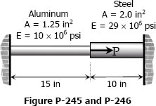
Referring to the composite bar in Problem 245, what maximum axial load P can be applied if the allowable stresses are 10 ksi for aluminum and 18 ksi for steel.
- Read more about Solution to Problem 246 Statically Indeterminate
- Log in or register to post comments


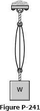 As shown in Fig. P-241, three steel wires, each 0.05 in.2 in area, are used to lift a load W = 1500 lb. Their unstressed lengths are 74.98 ft, 74.99 ft, and 75.00 ft.
